Cisco VG224 Hardware Installation Guide - Page 23
Physical Description and LEDs - phone gateway
 |
UPC - 746320575360
View all Cisco VG224 manuals
Add to My Manuals
Save this manual to your list of manuals |
Page 23 highlights
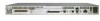
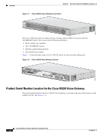
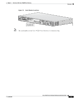
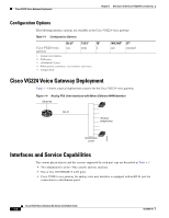
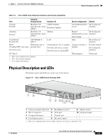
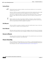
Chapter 1 Overview of the Cisco VG224 Voice Gateway Physical Description and LEDs Table 1-2 Cisco VG224 Voice Gateway Interfaces and Service Capabilities Port Console Port 0/0 Auxiliary Port 0/1 Interface Configurations EIA/TIA-232 asynchronous serial (DCE1) EIA/TIA-232 asynchronous serial (DTE2) Interface To ASCII terminal Personal computer Modem Fast Ethernet Port 0/0, 0/1 10/100BASE-T (802.3) RJ-21 FXS (loop-start or 24 analog FXS voice ports ground-start) Port 2/0 to 2/23 CF3 Slot 0 1. DCE = data communications equipment 2. DTE = data terminal equipment 3. CF = compact flash memory LAN Analog phone, fax, or modem Network side of key system Network side of analog PBX Services Supported Details Local administrative RJ-45 physical access interface Remote RJ-45 physical administrative access interface Data backup Data RJ-45 physical interface Analog voice/fax or modem Provides battery RJ-21 physical interface Flash memory Flash card Physical Description and LEDs All interface ports and LEDs are on the rear of the chassis. Figure 1-5 Cisco VG224 Voice Gateway LEDs 95914 OL-5006-04 1 2 VG224-24FXS 3 4 56 8 9 7 10 1 Chassis ground connection 5 Fast Ethernet port 0 9 On/off switch 2 RJ-21 connector 3 Compact flash port 4 Fast Ethernet port 1 6 AUX port 7 Console port 8 DC power input1 10 AC power input 1. This is not a redundant failover power supply connection. You must use either DC or AC. Cisco VG224 Voice Gateway Hardware Installation Guide 1-5
-
 1
1 -
2
-
3
-
4
-
5
-
6
-
7
-
8
-
9
-
10
-
11
-
12
-
13
-
14
-
15
-
16
-
17
-
 18
18 -
 19
19 -
 20
20 -
 21
21 -
 22
22 -
 23
23 -
 24
24 -
 25
25 -
 26
26 -
 27
27 -
 28
28 -
29
-
30
-
31
-
32
-
33
-
34
-
35
-
36
-
37
-
38
-
39
-
40
-
41
-
42
-
43
-
44
-
45
-
46
-
47
-
48
-
49
-
50
-
51
-
52
-
53
-
54
-
55
-
56
-
57
-
58
-
59
-
60
-
61
-
62
-
63
-
64
-
65
-
66
-
67
-
68
-
69
-
70
-
71
-
72
-
73
-
74
-
75
 |
 |