Cisco VG224 Hardware Installation Guide - Page 65
Console Port to PC, Console Port, DCE, RJ-45, RJ-45-to-RJ-45, Rollover Cable, Adapter TERMINAL
 |
UPC - 746320575360
View all Cisco VG224 manuals
Add to My Manuals
Save this manual to your list of manuals |
Page 65 highlights
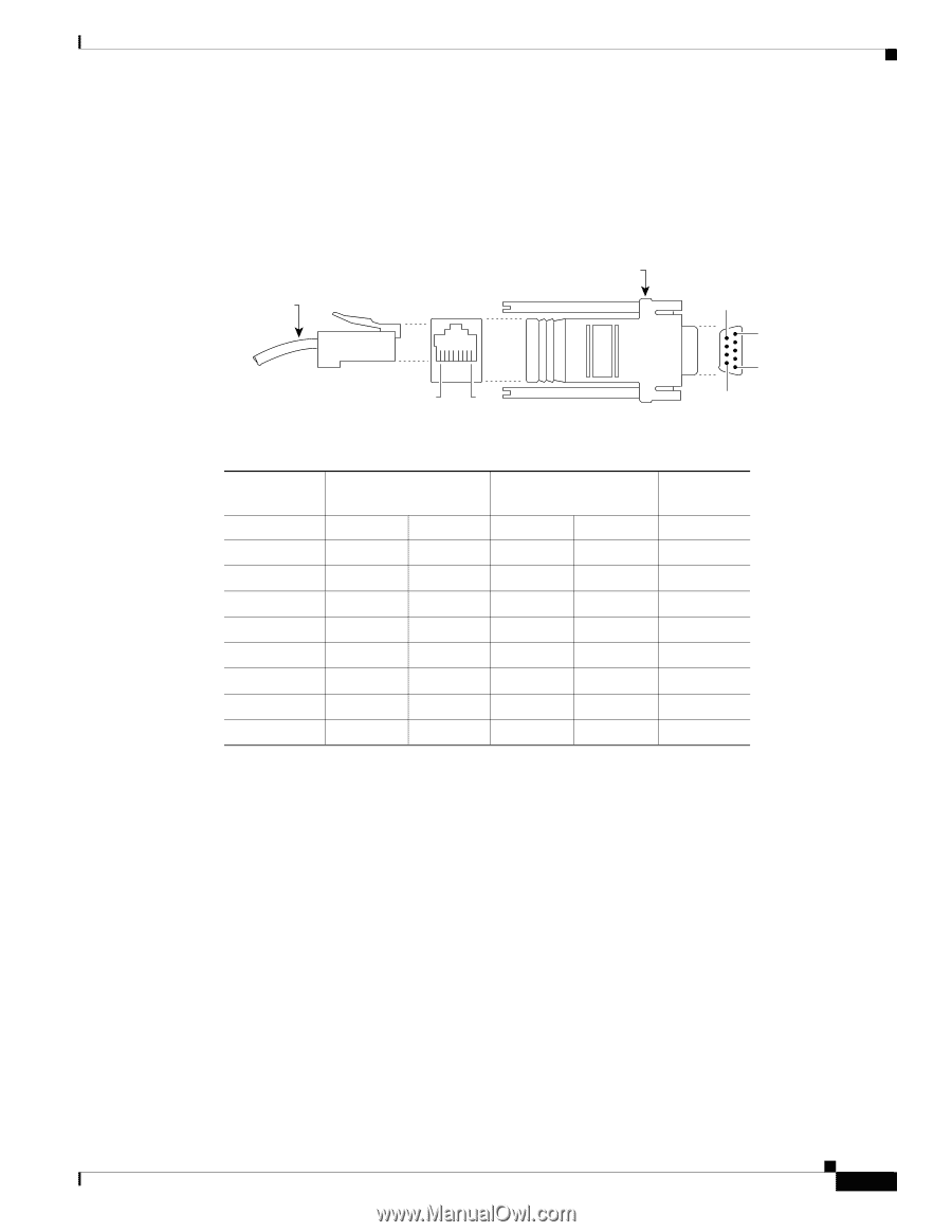
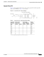
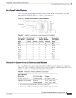
Appendix A Cable Specifications and Information Console and Auxiliary Port Cables and Pinouts Console Port to PC Figure A-2 shows the RJ-45-to-RJ-45 rollover cable assembly and the RJ-45-to-DB-9 female DTE adapter (labeled TERMINAL); Table A-1 lists the pinouts. Figure A-2 Console Port to PC-Cable and Adapter RJ-45-to-DB-9 female adapter RJ-45 cable 8 1 9 5 1 6 TERMINAL H11192 Table A-1 Console Port to PC-Cable Pinouts (RJ-45 to DB-9) Console Port RJ-45-to-RJ-45 (DCE, RJ-45) Rollover Cable RJ-45-to-DB-9 Adapter "TERMINAL" Signal RTS RJ-45 Pin 11 RJ-45 Pin 8 RJ-45 Pin 8 DB-9 Pin 8 DTR 2 7 7 6 TxD 3 6 6 2 GND 4 5 5 5 GND 5 4 4 5 RxD 6 3 3 3 DSR 7 2 2 4 CTS 81 1 1 7 1. Pin 1 is connected to pin 8 inside the Cisco VG224 voice gateway. PC Port (DTE, DB-9) Signal CTS DSR RxD GND GND TxD DTR RTS OL-5006-04 Cisco VG224 Voice Gateway Hardware Installation Guide A-3
-
 1
1 -
2
-
3
-
4
-
5
-
6
-
7
-
8
-
9
-
10
-
11
-
12
-
13
-
14
-
15
-
16
-
17
-
18
-
19
-
20
-
21
-
22
-
23
-
24
-
25
-
26
-
27
-
28
-
29
-
30
-
31
-
32
-
33
-
34
-
35
-
36
-
37
-
38
-
39
-
40
-
41
-
42
-
43
-
44
-
45
-
46
-
47
-
48
-
49
-
50
-
51
-
52
-
53
-
54
-
55
-
56
-
57
-
58
-
59
-
 60
60 -
 61
61 -
 62
62 -
 63
63 -
 64
64 -
 65
65 -
 66
66 -
 67
67 -
 68
68 -
 69
69 -
 70
70 -
71
-
72
-
73
-
74
-
75
 |
 |