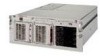
Compaq DL580 Service Guide - Page 187
Power On/Standby switch, frequency range
 |
UPC - 720591733483
View all Compaq DL580 manuals
Add to My Manuals
Save this manual to your list of manuals |
Page 187 highlights
12 Compaq ProLiant DL580 Server Maintenance and Service Guide canceling an action 2-38 illustrated 2-38 expansion board removing 2-37 removing, illustrated 2-39 replacing 2-39 LED switchboard and cable part number 1-6 removing 2-42 removing, illustrated 2-42 replacing 2-42 non-hot-plug expansion board, replacing 2-40 slots controlling 2-36 identified 4-3 illustrated 2-36 switchboard LEDs description 4-17 illustrated 4-17 status indicators 4-17 peripheral board configuration switch (SW1), settings 4-7 configuration switch, illustrated 4-7 connectors, identified 4-4 connectors, illustrated 4-4 part number 1-6 removing 2-28 removing, illustrated 2-28 replacing 2-28 plastics kit, part number 1-3 pointing device interface, test error codes 3-32 POST beeps, description 3-8 defined 3-7 error messages 3-7 power backplane board cable routing 2-22 connectors, identified 4-5 connectors, illustrated 4-5 part number 1-6 removing 2-44 removing, illustrated 2-44 replacing 2-44 power cable assembly part number 1-6 removing 2-47 removing from chassis, illustrated 2-47 removing ground wire screw 2-48 replacing 2-49 unplugging from power backplane board 2-48 Power On/Standby switch disconnecting, illustrated 2-9 positions 2-4 removing 2-9 removing, illustrated 2-10 replacing 2-10 power status indicator, defined 4-17 power supply blank cover, part number 1-3 cables, removing 2-47 connector, identified 4-5 connector, removing, illustrated 2-49 connectors, identified 4-5 dielectric voltage 5-4 frequency range 5-4 input transient susceptibility 5-4 input voltage specifications 5-4 LEDs, identifying 4-15 LEDs, illustrated 4-15 minimum load 5-4 overview 4-15 part number 1-5 power factor 5-4 rear panel connector, identified 4-2 removing 2-24 removing,illustrated 2-24 replacing 2-24 temperature range 5-4 voltage input 5-4 power switch LEDs, illustrated 4-12 positions 2-4 removing, illustrated 2-10 Power-On Self-Test See POST preparation procedures hot-pluggable parts 2-4 non-hot-pluggable parts 2-4 powering down server 2-5 rack warnings 2-6 server warnings and precautions 2-7 processor and processor terminator modules description, identification 2-25 location, illustrated 2-25 processor cage part number 1-6 removing 2-46 removing, illustrated 2-46 replacing 2-46 processor core frequency switch (SW4), illustrated 4-9
-
 1
1 -
2
-
3
-
4
-
5
-
6
-
7
-
8
-
9
-
10
-
11
-
12
-
13
-
14
-
15
-
16
-
17
-
18
-
19
-
20
-
21
-
22
-
23
-
24
-
25
-
26
-
27
-
28
-
29
-
30
-
31
-
32
-
33
-
34
-
35
-
36
-
37
-
38
-
39
-
40
-
41
-
42
-
43
-
44
-
45
-
46
-
47
-
48
-
49
-
50
-
51
-
52
-
53
-
54
-
55
-
56
-
57
-
58
-
59
-
60
-
61
-
62
-
63
-
64
-
65
-
66
-
67
-
68
-
69
-
70
-
71
-
72
-
73
-
74
-
75
-
76
-
77
-
78
-
79
-
80
-
81
-
82
-
83
-
84
-
85
-
86
-
87
-
88
-
89
-
90
-
91
-
92
-
93
-
94
-
95
-
96
-
97
-
98
-
99
-
100
-
101
-
102
-
103
-
104
-
105
-
106
-
107
-
108
-
109
-
110
-
111
-
112
-
113
-
114
-
115
-
116
-
117
-
118
-
119
-
120
-
121
-
122
-
123
-
124
-
125
-
126
-
127
-
128
-
129
-
130
-
131
-
132
-
133
-
134
-
135
-
136
-
137
-
138
-
139
-
140
-
141
-
142
-
143
-
144
-
145
-
146
-
147
-
148
-
149
-
150
-
151
-
152
-
153
-
154
-
155
-
156
-
157
-
158
-
159
-
160
-
161
-
162
-
163
-
164
-
165
-
166
-
167
-
168
-
169
-
170
-
171
-
172
-
173
-
174
-
175
-
176
-
177
-
178
-
179
-
180
-
181
-
 182
182 -
 183
183 -
 184
184 -
 185
185 -
 186
186 -
 187
187 -
 188
188 -
 189
189 -
 190
190 -
 191
191 -
 192
192 -
193
 |
 |
