Compaq Portable 286 Compaq Portable Computer, Compaq Plus Personal Computer, a - Page 53
Removal and Replacement Procedures, Introduction
 |
View all Compaq Portable 286 manuals
Add to My Manuals
Save this manual to your list of manuals |
Page 53 highlights
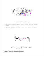
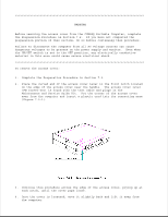
Chapter 7. Removal and Replacement Procedures Chapter 7.1 Introduction Before starting removal procedures, review Chapter 6, "Illustrated Parts Catalog," to become familiar with the various part names and locations. Removal and replacement procedures in this section are written generically for all COMPAQ Portable Computers, except in cases where procedures differ because of design differences. These differences affect the removal and replacement procedures for the power supply subsystem and the monitor enclosure. When procedures differ, specific instructions are given. Also note that when you are instructed to cut a tie wrap for removal of an assembly, you should also replace the tie wrap for reassembly. NOTE: Run the latest version of COMPAQ DIAGNOSTICS to verify the proper operation of the replaced component. Chapter 7.2 Preparation Procedure Before beginning the procedures in this section, complete the following steps: 1. Place the ON/OFF switch (on the side of the computer) in the OFF position. 2. Close the keyboard and secure it in place by sliding the latches to the LOCK position. Fold the keyboard feet in place. (Figure 7.2-1).
-
 1
1 -
2
-
3
-
4
-
5
-
6
-
7
-
8
-
9
-
10
-
11
-
12
-
13
-
14
-
15
-
16
-
17
-
18
-
19
-
20
-
21
-
22
-
23
-
24
-
25
-
26
-
27
-
28
-
29
-
30
-
31
-
32
-
33
-
34
-
35
-
36
-
37
-
38
-
39
-
40
-
41
-
42
-
43
-
44
-
45
-
46
-
47
-
 48
48 -
 49
49 -
 50
50 -
 51
51 -
 52
52 -
 53
53 -
 54
54 -
 55
55 -
 56
56 -
 57
57 -
 58
58 -
59
-
60
-
61
-
62
-
63
-
64
-
65
-
66
-
67
-
68
-
69
-
70
-
71
-
72
-
73
-
74
-
75
-
76
-
77
-
78
-
79
-
80
-
81
-
82
-
83
-
84
-
85
-
86
-
87
-
88
-
89
-
90
-
91
-
92
-
93
-
94
-
95
-
96
-
97
-
98
-
99
-
100
-
101
-
102
-
103
-
104
-
105
-
106
-
107
-
108
-
109
-
110
-
111
-
112
-
113
-
114
-
115
-
116
-
117
-
118
-
119
-
120
-
121
-
122
-
123
-
124
-
125
-
126
-
127
-
128
-
129
 |
 |
