Compaq Portable 286 Compaq Portable Computer, Compaq Plus Personal Computer, a - Page 57
High Voltage Access Plate Removal and Replacement
 |
View all Compaq Portable 286 manuals
Add to My Manuals
Save this manual to your list of manuals |
Page 57 highlights
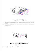
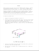
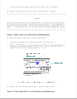
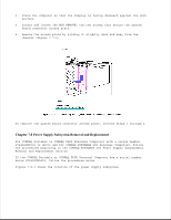
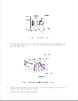
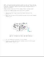
up from the system chassis and lifting it away from the computer. To replace the board slots access plate, reverse Steps 1 through 3 CAUTION Ensure that the retainers on the bottom side of the board slots access plate fit securely onto each board installed in your computer. If you changed to a board of a different height, rotate the retainers to match the height of the board. If the retainers are not rotated, serious internal damage may result Chapter 7.5 High Voltage Access Plate Removal and Replacement To remove and replace the high voltage access plate: 1. Complete the Access Cover Removal Procedure (see Section 7.3). 2. Loosen (DO NOT REMOVE) the six screws and the two 1/4 inch nuts securing the high voltage access plate (Figure 7.5-1). Slide the metal cover toward the rear of the computer and lift it off. To replace the high voltage access plate, reverse Steps 1 and 2. Chapter 7.6 Mass Storage Device Access Plate Removal and Replacement
-
 1
1 -
2
-
3
-
4
-
5
-
6
-
7
-
8
-
9
-
10
-
11
-
12
-
13
-
14
-
15
-
16
-
17
-
18
-
19
-
20
-
21
-
22
-
23
-
24
-
25
-
26
-
27
-
28
-
29
-
30
-
31
-
32
-
33
-
34
-
35
-
36
-
37
-
38
-
39
-
40
-
41
-
42
-
43
-
44
-
45
-
46
-
47
-
48
-
49
-
50
-
51
-
 52
52 -
 53
53 -
 54
54 -
 55
55 -
 56
56 -
 57
57 -
 58
58 -
 59
59 -
 60
60 -
 61
61 -
 62
62 -
63
-
64
-
65
-
66
-
67
-
68
-
69
-
70
-
71
-
72
-
73
-
74
-
75
-
76
-
77
-
78
-
79
-
80
-
81
-
82
-
83
-
84
-
85
-
86
-
87
-
88
-
89
-
90
-
91
-
92
-
93
-
94
-
95
-
96
-
97
-
98
-
99
-
100
-
101
-
102
-
103
-
104
-
105
-
106
-
107
-
108
-
109
-
110
-
111
-
112
-
113
-
114
-
115
-
116
-
117
-
118
-
119
-
120
-
121
-
122
-
123
-
124
-
125
-
126
-
127
-
128
-
129
 |
 |
