Dell Alienware m15 R6 Service Manual - Page 38
Memory module, Removing the memory module
 |
View all Dell Alienware m15 R6 manuals
Add to My Manuals
Save this manual to your list of manuals |
Page 38 highlights
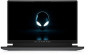
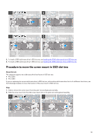
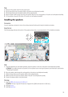
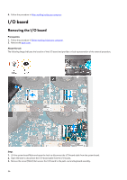
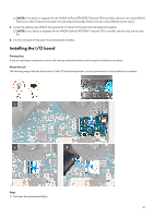
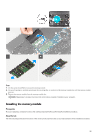
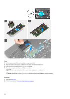
2. Align and place the I/O board on the palm-rest and keyboard assembly. 3. Replace the screw (M2x4) that secures the I/O board to the palm-rest and keyboard assembly. NOTE: If the device is shipped with the NVIDIA GeForce RTX 3050 Ti discrete GPU controller, replace the two screws (M2x4) that secure the I/O board to the palm-rest and keyboard assembly. See step 5. 4. Tighten the captive screw (M2x2) that secures the I/O board to the palm-rest and keyboard assembly. NOTE: If the device is shipped with the NVIDIA GeForce RTX 3050 Ti discrete GPU controller, skip this step and see step 5. 5. Connect the I/O-board cable to the I/O board and close the latch to secure the cable. 6. Connect the I/O-board cable to the system board and close the latch to secure the cable. 7. Place the system board Mylar back on the system board. Next steps 1. Install the base cover. 2. Follow the procedure in After working inside your computer. Memory module Removing the memory module Prerequisites 1. Follow the procedure in Before working inside your computer. 2. Remove the base cover. About this task The following image indicates the location of the memory module and provides a visual representation of the removal procedure. 38
-
 1
1 -
2
-
3
-
4
-
5
-
6
-
7
-
8
-
9
-
10
-
11
-
12
-
13
-
14
-
15
-
16
-
17
-
18
-
19
-
20
-
21
-
22
-
23
-
24
-
25
-
26
-
27
-
28
-
29
-
30
-
31
-
32
-
 33
33 -
 34
34 -
 35
35 -
 36
36 -
 37
37 -
 38
38 -
 39
39 -
 40
40 -
 41
41 -
 42
42 -
 43
43 -
44
-
45
-
46
-
47
-
48
-
49
-
50
-
51
-
52
-
53
-
54
-
55
-
56
-
57
-
58
-
59
-
60
-
61
-
62
-
63
-
64
-
65
-
66
-
67
-
68
-
69
-
70
-
71
-
72
-
73
-
74
-
75
-
76
-
77
-
78
-
79
-
80
-
81
-
82
-
83
-
84
-
85
-
86
-
87
-
88
-
89
-
90
-
91
-
92
 |
 |