Dell Alienware m15 R6 Service Manual - Page 43
Rear-I/O cover, Removing the rear I/O-cover
 |
View all Dell Alienware m15 R6 manuals
Add to My Manuals
Save this manual to your list of manuals |
Page 43 highlights
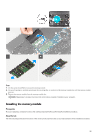
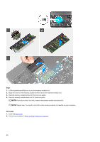
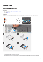
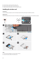
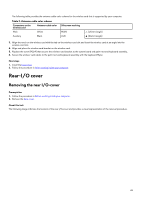
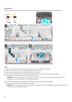
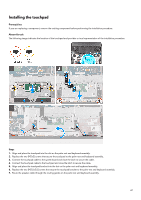
The following table provides the antenna-cable color scheme for the wireless card that is supported by your computer. Table 2. Antenna-cable color scheme Connectors on the wireless card Antenna-cable color Main White Auxiliary Black Silkscreen marking MAIN AUX △ (white triangle) ▲ (black triangle) 3. Align the notch on the wireless card with the tab on the wireless-card slot and insert the wireless card at an angle into the wireless-card slot. 4. Align and place the wireless-card bracket on the wireless card. 5. Replace the screw (M2x4) that secures the wireless-card bracket to the system board and palm-rest and keyboard assembly. 6. Secure the wireless-card cables to the palm-rest and keyboard assembly with the keyboard Mylar. Next steps 1. Install the base cover. 2. Follow the procedure in After working inside your computer. Rear-I/O cover Removing the rear I/O-cover Prerequisites 1. Follow the procedure in Before working inside your computer. 2. Remove the base cover. About this task The following image indicates the location of the rear I/O-cover and provides a visual representation of the removal procedure. 43
-
 1
1 -
2
-
3
-
4
-
5
-
6
-
7
-
8
-
9
-
10
-
11
-
12
-
13
-
14
-
15
-
16
-
17
-
18
-
19
-
20
-
21
-
22
-
23
-
24
-
25
-
26
-
27
-
28
-
29
-
30
-
31
-
32
-
33
-
34
-
35
-
36
-
37
-
 38
38 -
 39
39 -
 40
40 -
 41
41 -
 42
42 -
 43
43 -
 44
44 -
 45
45 -
 46
46 -
 47
47 -
 48
48 -
49
-
50
-
51
-
52
-
53
-
54
-
55
-
56
-
57
-
58
-
59
-
60
-
61
-
62
-
63
-
64
-
65
-
66
-
67
-
68
-
69
-
70
-
71
-
72
-
73
-
74
-
75
-
76
-
77
-
78
-
79
-
80
-
81
-
82
-
83
-
84
-
85
-
86
-
87
-
88
-
89
-
90
-
91
-
92
 |
 |