Dell Alienware m15 R6 Service Manual - Page 62
I/O-board cable, About this task
 |
View all Dell Alienware m15 R6 manuals
Add to My Manuals
Save this manual to your list of manuals |
Page 62 highlights
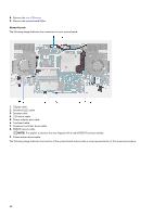
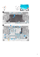
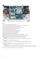
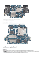
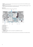
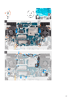
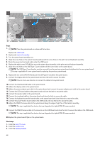
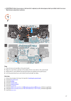
NOTE: Your computer's Service Tag is stored in the system board. You must enter the Service Tag in the BIOS setup program after you replace the system board. NOTE: Replacing the system board removes any changes you have made to the BIOS using the BIOS setup program. You must make the appropriate changes again after you replace the system board. About this task The following image indicates the connectors on your system board. 1. Display cable 2. Alienhead LED cable 3. Speaker cable 4. I/O-board cable 5. Power-adapter port cable 6. Touchpad cable 7. Keyboard cable 8. RGB-IR camera cable NOTE: This applies to devices that are shipped with a hybrid RGB-IR camera module. 9. Power button cable The following image indicates the location of the system board and provides a visual representation of the installation procedure. 62
-
 1
1 -
2
-
3
-
4
-
5
-
6
-
7
-
8
-
9
-
10
-
11
-
12
-
13
-
14
-
15
-
16
-
17
-
18
-
19
-
20
-
21
-
22
-
23
-
24
-
25
-
26
-
27
-
28
-
29
-
30
-
31
-
32
-
33
-
34
-
35
-
36
-
37
-
38
-
39
-
40
-
41
-
42
-
43
-
44
-
45
-
46
-
47
-
48
-
49
-
50
-
51
-
52
-
53
-
54
-
55
-
56
-
 57
57 -
 58
58 -
 59
59 -
 60
60 -
 61
61 -
 62
62 -
 63
63 -
 64
64 -
 65
65 -
 66
66 -
 67
67 -
68
-
69
-
70
-
71
-
72
-
73
-
74
-
75
-
76
-
77
-
78
-
79
-
80
-
81
-
82
-
83
-
84
-
85
-
86
-
87
-
88
-
89
-
90
-
91
-
92
 |
 |