Dell Alienware m15 R6 Service Manual - Page 50
Display assembly, Removing the display assembly
 |
View all Dell Alienware m15 R6 manuals
Add to My Manuals
Save this manual to your list of manuals |
Page 50 highlights
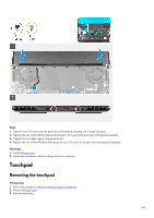
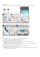
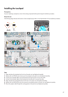
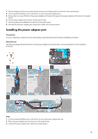
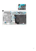
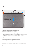
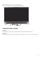
4. Adhere the power-adapter port cable on the system board. 5. Align the screw holes on the power-adapter port bracket to the screw holes on the system board. 6. Replace the two screws (M2x4) that secure the power-adapter port bracket to the system board. 7. Replace the system board Mylar back to the edge of the left fan. 8. Route the display cable through the opening between the power-adapter port and the heat-sink assembly. 9. Connect the display cable on the system board and close the latch to secure the cable. 10. Connect the Alienhead LED cable to the system board. 11. Adhere the display cable to the system board. Next steps 1. Install the rear I/O-cover. 2. Install the base cover. 3. Follow the procedure in After working inside your computer. Display assembly Removing the display assembly Prerequisites 1. Follow the procedure in Before working inside your computer. 2. Remove the base cover. 3. Remove the rear I/O-cover. About this task The following images indicate the location of the display assembly and provide a visual representation of the removal procedure. 50
-
 1
1 -
2
-
3
-
4
-
5
-
6
-
7
-
8
-
9
-
10
-
11
-
12
-
13
-
14
-
15
-
16
-
17
-
18
-
19
-
20
-
21
-
22
-
23
-
24
-
25
-
26
-
27
-
28
-
29
-
30
-
31
-
32
-
33
-
34
-
35
-
36
-
37
-
38
-
39
-
40
-
41
-
42
-
43
-
44
-
 45
45 -
 46
46 -
 47
47 -
 48
48 -
 49
49 -
 50
50 -
 51
51 -
 52
52 -
 53
53 -
 54
54 -
 55
55 -
56
-
57
-
58
-
59
-
60
-
61
-
62
-
63
-
64
-
65
-
66
-
67
-
68
-
69
-
70
-
71
-
72
-
73
-
74
-
75
-
76
-
77
-
78
-
79
-
80
-
81
-
82
-
83
-
84
-
85
-
86
-
87
-
88
-
89
-
90
-
91
-
92
 |
 |