Dell Alienware m15 R6 Service Manual - Page 58
Alienhead LED cable, I/O-board cable
 |
View all Dell Alienware m15 R6 manuals
Add to My Manuals
Save this manual to your list of manuals |
Page 58 highlights
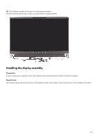
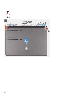
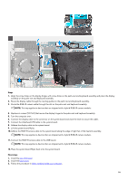
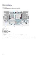
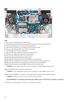
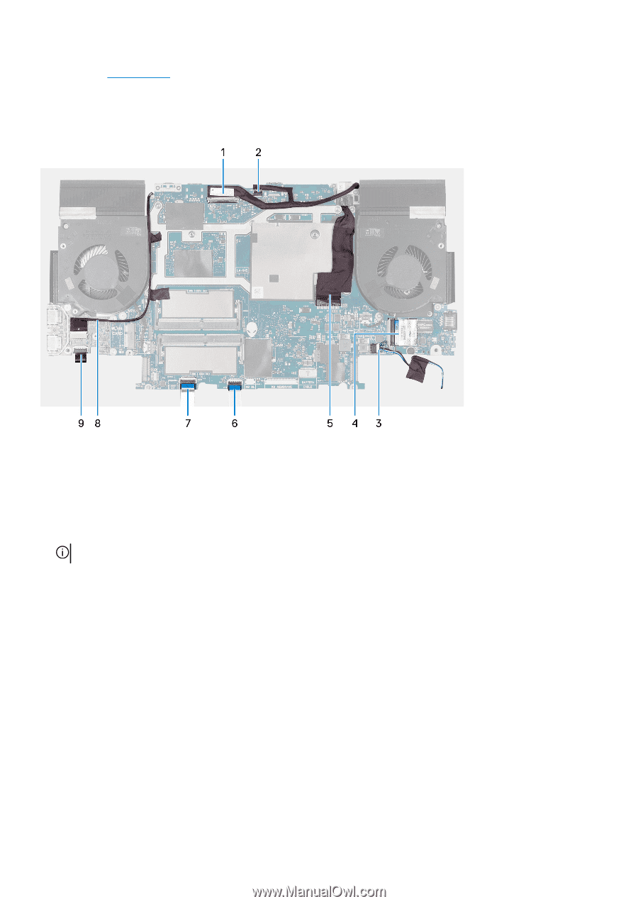
8. Remove the rear I/O-cover. 9. Remove the system board Mylar. About this task The following image indicates the connectors on your system board. 1. Display cable 2. Alienhead LED cable 3. Speaker cable 4. I/O-board cable 5. Power-adapter port cable 6. Touchpad cable 7. Keyboard-controller board cable 8. RGB-IR camera cable NOTE: This applies to devices that are shipped with a hybrid RGB-IR camera module. 9. Power-button board cable The following image indicates the location of the system board and provides a visual representation of the removal procedure. 58
-
 1
1 -
2
-
3
-
4
-
5
-
6
-
7
-
8
-
9
-
10
-
11
-
12
-
13
-
14
-
15
-
16
-
17
-
18
-
19
-
20
-
21
-
22
-
23
-
24
-
25
-
26
-
27
-
28
-
29
-
30
-
31
-
32
-
33
-
34
-
35
-
36
-
37
-
38
-
39
-
40
-
41
-
42
-
43
-
44
-
45
-
46
-
47
-
48
-
49
-
50
-
51
-
52
-
 53
53 -
 54
54 -
 55
55 -
 56
56 -
 57
57 -
 58
58 -
 59
59 -
 60
60 -
 61
61 -
 62
62 -
 63
63 -
64
-
65
-
66
-
67
-
68
-
69
-
70
-
71
-
72
-
73
-
74
-
75
-
76
-
77
-
78
-
79
-
80
-
81
-
82
-
83
-
84
-
85
-
86
-
87
-
88
-
89
-
90
-
91
-
92
 |
 |
8.
Remove the
rear I/O-cover
.
9.
Remove the system board Mylar.
About this task
The following image indicates the connectors on your system board.
1.
Display cable
2.
Alienhead LED cable
3.
Speaker cable
4.
I/O-board cable
5.
Power-adapter port cable
6.
Touchpad cable
7.
Keyboard-controller board cable
8.
RGB-IR camera cable
NOTE:
This applies to devices that are shipped with a hybrid RGB-IR camera module.
9.
Power-button board cable
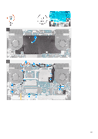
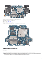
The following image indicates the location of the system board and provides a visual representation of the removal procedure.
58