Dell Alienware m15 R6 Service Manual - Page 64
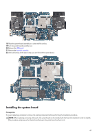
Connect the speaker cable to the system board.
 |
View all Dell Alienware m15 R6 manuals
Add to My Manuals
Save this manual to your list of manuals |
Page 64 highlights
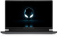
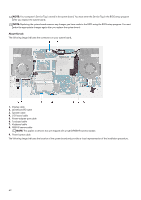
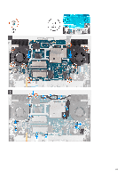
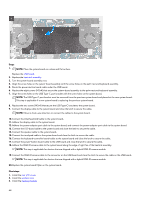
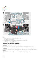
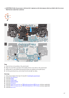
Steps 1. NOTE: Place the system board on a clean and flat surface. Replace the USB board. 2. Replace the heat-sink assembly. 3. Turn the system-board assembly over. 4. Align the screw holes on the system-board assembly with the screw holes on the palm-rest and keyboard assembly. 5. Route the power-button board cable under the USB board. 6. Replace the eight screws (M2x4) that secure the system-board assembly to the palm-rest and keyboard assembly. 7. Align the screw holes on the USB Type-C port bracket with the screw holes on the system board. NOTE: The USB Type-C port bracket must be removed from the previous system board and placed at the new system board. This step is applicable if a new system board is replacing the previous system board. 8. Replace the two screws (M2x4) that secure the USB Type-C bracket to the system board. 9. Connect the display cable to the system board and close the latch to secure the cable. NOTE: Move in clock-wise direction to connect the cables to the system board. 10. Connect the Alienhead LED cable to the system board. 11. Adhere the display cable to the system board. 12. Adhere the power-adapter port cable to the system board, and connect the power-adapter port cable to the system board. 13. Connect the I/O-board cable to the system board and close the latch to secure the cable. 14. Connect the speaker cable to the system board. 15. Connect the touchpad cable to the system board and close the latch to secure the cable. 16. Connect the keyboard-controller board-cable to the system board and close the latch to secure the cable. 17. Connect the power-button board cable to the USB board and close the latch to secure the cable. 18. Adhere the RGB-IR camera cable to the system board along the edge of right fan of the heatsink assembly. NOTE: This step is applicable for devices that are shipped with a hybrid RGB-IR camera module. 19. Connect the RGB-IR camera cable to the connector on the USB board and close the latch to secure the cable on the USB board. NOTE: This step is applicable for devices that are shipped with a hybrid RGB-IR camera module. 20.Replace the system board Mylar on the system board. Next steps 1. Install the rear I/O-cover. 2. Install the wireless card. 3. Install the memory module. 64
-
 1
1 -
2
-
3
-
4
-
5
-
6
-
7
-
8
-
9
-
10
-
11
-
12
-
13
-
14
-
15
-
16
-
17
-
18
-
19
-
20
-
21
-
22
-
23
-
24
-
25
-
26
-
27
-
28
-
29
-
30
-
31
-
32
-
33
-
34
-
35
-
36
-
37
-
38
-
39
-
40
-
41
-
42
-
43
-
44
-
45
-
46
-
47
-
48
-
49
-
50
-
51
-
52
-
53
-
54
-
55
-
56
-
57
-
58
-
 59
59 -
 60
60 -
 61
61 -
 62
62 -
 63
63 -
 64
64 -
 65
65 -
 66
66 -
 67
67 -
 68
68 -
 69
69 -
70
-
71
-
72
-
73
-
74
-
75
-
76
-
77
-
78
-
79
-
80
-
81
-
82
-
83
-
84
-
85
-
86
-
87
-
88
-
89
-
90
-
91
-
92
 |
 |