Dell Alienware m15 R6 Service Manual - Page 55
Lift the system board Mylar., Adhere the display cable to the system board.
 |
View all Dell Alienware m15 R6 manuals
Add to My Manuals
Save this manual to your list of manuals |
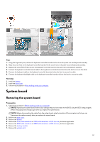
Page 55 highlights
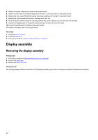
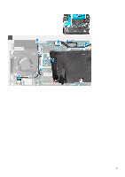
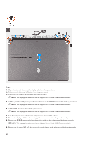
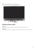
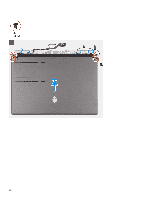
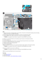
Steps 1. Align the screw holes on the display hinges with screw holes on the palm-rest and keyboard assembly and place the display assembly on the palm-rest and keyboard assembly. 2. Route the display cable through the routing guides on the palm-rest and keyboard assembly. 3. Route the RGB-IR camera cable through the slot on the palm-rest and keyboard assembly. NOTE: This step applies to devices that are shipped with a hybrid RGB-IR camera module. 4. Replace six screws (M2.5x5) that secure the display hinges to the palm-rest and keyboard assembly. 5. Turn the computer over. 6. Connect the display cable to the connector on the system board and close the latch to secure the cable. 7. Connect the Alienhead LED cable to the system board. 8. Adhere the display cable to the system board. 9. Lift the system board Mylar. 10. Adhere the RGB-IR camera cable to the system board along the edge of right fan of the heatsink assembly. NOTE: This step applies to devices that are shipped with a hybrid RGB-IR camera module. 11. Connect the RGB-IR camera cable to the USB board. NOTE: This step applies to devices that are shipped with a hybrid RGB-IR camera module. 12. Place the system board Mylar back onto the system board. Next steps 1. Install the rear I/O-cover. 2. Install the base cover. 3. Follow the procedure in After working inside your computer. 55
-
 1
1 -
2
-
3
-
4
-
5
-
6
-
7
-
8
-
9
-
10
-
11
-
12
-
13
-
14
-
15
-
16
-
17
-
18
-
19
-
20
-
21
-
22
-
23
-
24
-
25
-
26
-
27
-
28
-
29
-
30
-
31
-
32
-
33
-
34
-
35
-
36
-
37
-
38
-
39
-
40
-
41
-
42
-
43
-
44
-
45
-
46
-
47
-
48
-
49
-
 50
50 -
 51
51 -
 52
52 -
 53
53 -
 54
54 -
 55
55 -
 56
56 -
 57
57 -
 58
58 -
 59
59 -
 60
60 -
61
-
62
-
63
-
64
-
65
-
66
-
67
-
68
-
69
-
70
-
71
-
72
-
73
-
74
-
75
-
76
-
77
-
78
-
79
-
80
-
81
-
82
-
83
-
84
-
85
-
86
-
87
-
88
-
89
-
90
-
91
-
92
 |
 |
