Dell Alienware m15 R6 Service Manual - Page 60
Steps, CAUTION: Before removing the system board
 |
View all Dell Alienware m15 R6 manuals
Add to My Manuals
Save this manual to your list of manuals |
Page 60 highlights
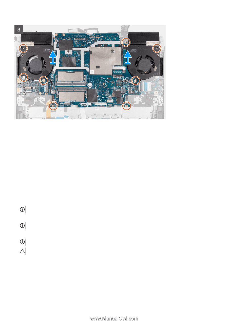
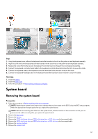
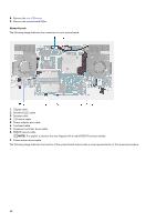
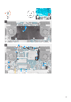
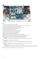
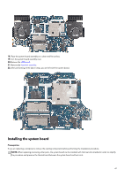
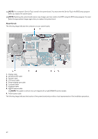
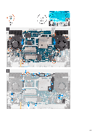
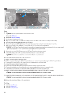
Steps 1. Peel the system board Mylar off the system board. 2. Remove the two screws (M2x4) that secure the USB Type-C port bracket to the system board. 3. Remove the USB Type-C port bracket from the system board. 4. Open the latch, and disconnect the display cable from the system board. 5. Disconnect the Alienhead LED cable from the system board. 6. Peel the display cable from the system board. 7. Disconnect the power-adapter port cable from the system board. 8. Peel the power-adapter port cable from the system board. 9. Disconnect the I/O-board cable from the system board. 10. Disconnect the speaker cable from the system board. 11. Open the latch, and disconnect the touchpad cable from the system board. 12. Open the latch, and disconnect the keyboard-controller board-cable from the system board. 13. Open the latch, and disconnect the power-button board cable from the USB board. 14. Open the latch, and disconnect the RGB-IR camera cable from the USB board. NOTE: This step is applicable for devices that are shipped with a hybrid RGB-IR camera module. 15. Peel the RGB-IR camera cable from the system board. NOTE: This step is applicable for devices that are shipped with a hybrid RGB-IR camera module. 16. Remove the eight (M2x4) screws that secure the system board to the palm-rest and keyboard assembly. NOTE: The USB board and heat sink are attached to the system board. CAUTION: Before removing the system board, give sufficient time for the heat sink to cool down to avoid injury. 17. Lift the system-board assembly off the palm-rest and keyboard assembly. 60
-
 1
1 -
2
-
3
-
4
-
5
-
6
-
7
-
8
-
9
-
10
-
11
-
12
-
13
-
14
-
15
-
16
-
17
-
18
-
19
-
20
-
21
-
22
-
23
-
24
-
25
-
26
-
27
-
28
-
29
-
30
-
31
-
32
-
33
-
34
-
35
-
36
-
37
-
38
-
39
-
40
-
41
-
42
-
43
-
44
-
45
-
46
-
47
-
48
-
49
-
50
-
51
-
52
-
53
-
54
-
 55
55 -
 56
56 -
 57
57 -
 58
58 -
 59
59 -
 60
60 -
 61
61 -
 62
62 -
 63
63 -
 64
64 -
 65
65 -
66
-
67
-
68
-
69
-
70
-
71
-
72
-
73
-
74
-
75
-
76
-
77
-
78
-
79
-
80
-
81
-
82
-
83
-
84
-
85
-
86
-
87
-
88
-
89
-
90
-
91
-
92
 |
 |