Dell Dimension 2200 Dell Dimension 2200 Owner's Manual - Page 66
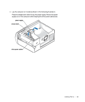
System Board, DIMM_A - video card
 |
View all Dell Dimension 2200 manuals
Add to My Manuals
Save this manual to your list of manuals |
Page 66 highlights
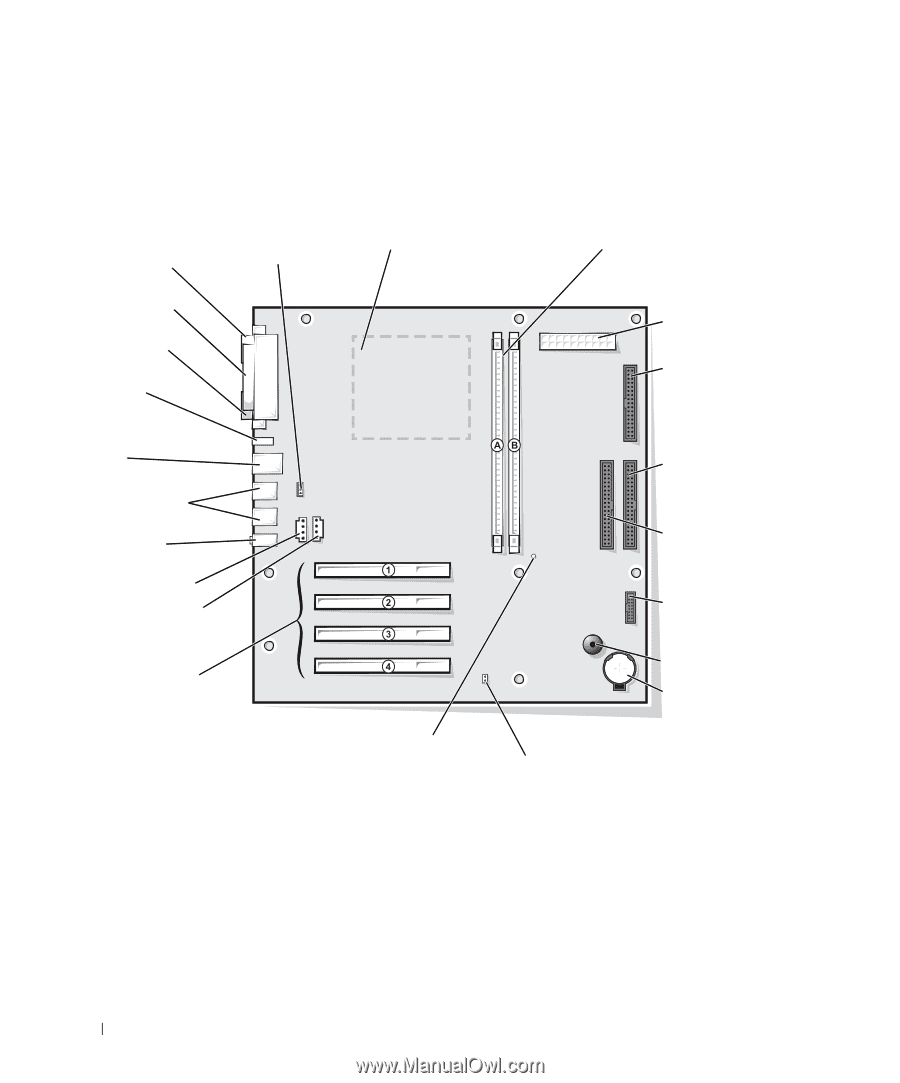
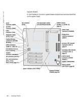
www.dell.com | support.dell.com System Board In the illustration, the text in parentheses indicates how items are identified on the system board. serial connector (SER) parallel connector (PAR) video connector (VID) diagnostic lights (DIAG LED) keyboard/mouse connectors (KEYBD MOUSE) USB connectors (USB 01, USB 23) microphone, line-out, line-in (AUDIO) modem connector (MODEM) CD connector (CD IN) PCI card connectors (PCI1, PCI2, PCI3, PCI4) page 73 fan connector (FAN) microprocessor socket (MICROPROCESSOR) DIMM sockets (DIMM_A, DIMM_B) page 78 power input connector (POWER) floppy drive interface connector (DSKT) power indicator (AUX PWR) primary IDE channel connector (IDE 1) page 67 secondary IDE channel connector (IDE 2) page 67 control panel connector (FRONT PANEL) speaker (SPEAKER) battery socket (BATTERY) page 89 password jumper (PSWD) page 88 66 A d d i n g Pa r ts
-
 1
1 -
2
-
3
-
4
-
5
-
6
-
7
-
8
-
9
-
10
-
11
-
12
-
13
-
14
-
15
-
16
-
17
-
18
-
19
-
20
-
21
-
22
-
23
-
24
-
25
-
26
-
27
-
28
-
29
-
30
-
31
-
32
-
33
-
34
-
35
-
36
-
37
-
38
-
39
-
40
-
41
-
42
-
43
-
44
-
45
-
46
-
47
-
48
-
49
-
50
-
51
-
52
-
53
-
54
-
55
-
56
-
57
-
58
-
59
-
60
-
 61
61 -
 62
62 -
 63
63 -
 64
64 -
 65
65 -
 66
66 -
 67
67 -
 68
68 -
 69
69 -
 70
70 -
 71
71 -
72
-
73
-
74
-
75
-
76
-
77
-
78
-
79
-
80
-
81
-
82
-
83
-
84
-
85
-
86
-
87
-
88
-
89
-
90
-
91
-
92
-
93
-
94
-
95
-
96
-
97
-
98
-
99
-
100
-
101
-
102
-
103
-
104
-
105
-
106
-
107
-
108
-
109
-
110
-
111
-
112
-
113
-
114
-
115
-
116
-
117
-
118
-
119
-
120
-
121
-
122
-
123
-
124
-
125
-
126
-
127
-
128
-
129
-
130
-
131
-
132
-
133
-
134
-
135
-
136
-
137
-
138
-
139
-
140
 |
 |