Dell Dimension 2200 Dell Dimension 2200 Owner's Manual - Page 79
it fits into the vertical guides at each end of the connector.
 |
View all Dell Dimension 2200 manuals
Add to My Manuals
Save this manual to your list of manuals |
Page 79 highlights
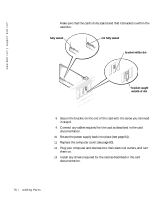
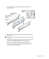
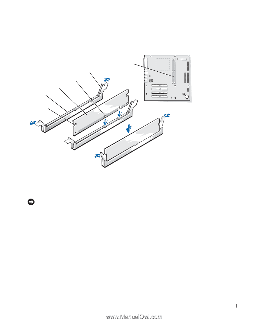
7 To insert a module, press out the securing clip at each end of the memory connector. securing clips (2) notches (2) memory module connector system board location cutouts (2) step 7 step 8 step 9 8 Align the notches on the bottom of the module with the crossbars in the connector. NOTICE: To avoid breaking the memory module, do not press near the middle of the module. 9 Insert the module straight down into the connector, making sure that it fits into the vertical guides at each end of the connector. Press firmly on the ends of the module until it snaps into place. If you insert the module correctly, the securing clips snap into the cutouts at each end of the module. Adding Pa rts 79
-
 1
1 -
2
-
3
-
4
-
5
-
6
-
7
-
8
-
9
-
10
-
11
-
12
-
13
-
14
-
15
-
16
-
17
-
18
-
19
-
20
-
21
-
22
-
23
-
24
-
25
-
26
-
27
-
28
-
29
-
30
-
31
-
32
-
33
-
34
-
35
-
36
-
37
-
38
-
39
-
40
-
41
-
42
-
43
-
44
-
45
-
46
-
47
-
48
-
49
-
50
-
51
-
52
-
53
-
54
-
55
-
56
-
57
-
58
-
59
-
60
-
61
-
62
-
63
-
64
-
65
-
66
-
67
-
68
-
69
-
70
-
71
-
72
-
73
-
 74
74 -
 75
75 -
 76
76 -
 77
77 -
 78
78 -
 79
79 -
 80
80 -
 81
81 -
 82
82 -
 83
83 -
 84
84 -
85
-
86
-
87
-
88
-
89
-
90
-
91
-
92
-
93
-
94
-
95
-
96
-
97
-
98
-
99
-
100
-
101
-
102
-
103
-
104
-
105
-
106
-
107
-
108
-
109
-
110
-
111
-
112
-
113
-
114
-
115
-
116
-
117
-
118
-
119
-
120
-
121
-
122
-
123
-
124
-
125
-
126
-
127
-
128
-
129
-
130
-
131
-
132
-
133
-
134
-
135
-
136
-
137
-
138
-
139
-
140
 |
 |
Adding Parts
79
7
To insert a module, press out the securing clip at each end of the
memory connector.
8
Align the notches on the bottom of the module with the crossbars in
the connector.
NOTICE:
To avoid breaking the memory module, do not press near the middle
of the module.
9
Insert the module straight down into the connector, making sure that
it fits into the vertical guides at each end of the connector.
Press firmly on the ends of the module until it snaps into place.
If you insert the module correctly, the securing clips snap into the
cutouts at each end of the module.
securing clips (2)
notches (2)
step 7
memory module
cutouts (2)
connector
step 8
step 9
system board
location