Dell Latitude XT2 XFR Service Manual - Page 67
Rocker Switch
 |
View all Dell Latitude XT2 XFR manuals
Add to My Manuals
Save this manual to your list of manuals |
Page 67 highlights
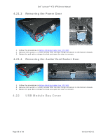
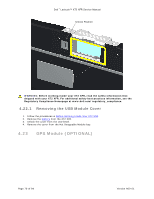
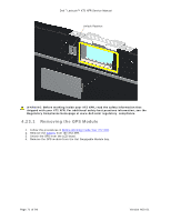
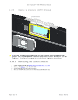
Dell™ Latitude™ XT2 XFR Service Manual 1 2 3 4 5 ID PCB Reference Wiring Color 1 WWAN - Back Black / Grey 2 GPS - Back Red 3 WLAN - Back Black 4 WWAN - Front Grey 5 WLAN - Front Black 2. Set the RF Passthru board on the chassis, insert and tighten the two (2 x 3-mm) screws. 3. Connect the grey and black mini-card cables into the barrel connectors on the opposite side and run them under the retainer tab. 4.20 Rocker Switch 4.20.1 Remove the Rocker Switch 1. Remove the screw (M2 x 3-mm) from the center of the rocker switch. 2. Pull the rocker switch with your finger until it disengages from the rocker pin. 4.20.2 Install the Rocker Switch 1. Insert the rocker switch onto the rocker pin. 2. Secure the screw holding the rocker switch to the pin. Page 67 of 94 Version A00-01
-
 1
1 -
2
-
3
-
4
-
5
-
6
-
7
-
8
-
9
-
10
-
11
-
12
-
13
-
14
-
15
-
16
-
17
-
18
-
19
-
20
-
21
-
22
-
23
-
24
-
25
-
26
-
27
-
28
-
29
-
30
-
31
-
32
-
33
-
34
-
35
-
36
-
37
-
38
-
39
-
40
-
41
-
42
-
43
-
44
-
45
-
46
-
47
-
48
-
49
-
50
-
51
-
52
-
53
-
54
-
55
-
56
-
57
-
58
-
59
-
60
-
61
-
 62
62 -
 63
63 -
 64
64 -
 65
65 -
 66
66 -
 67
67 -
 68
68 -
 69
69 -
 70
70 -
 71
71 -
 72
72 -
73
-
74
-
75
-
76
-
77
-
78
-
79
-
80
-
81
-
82
-
83
-
84
-
85
-
86
-
87
-
88
-
89
-
90
-
91
-
92
-
93
-
94
 |
 |
