Dell PowerEdge R440 EMC Installation and Service Manual 1 - Page 77
General memory module installation guidelines
 |
View all Dell PowerEdge R440 manuals
Add to My Manuals
Save this manual to your list of manuals |
Page 77 highlights
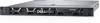
Figure 40. Memory socket locations Memory channels are organized as follows: Table 42. Memory channels Processor Processor 1 Processor 2 Channel 0 Slots A1 and A7 Slots B1 Channel 1 Channel 2 Slots A2 and A8 Slots A3 Slots B2 Slots B3 Channel 3 Slots A4 and A9 Slots B4 Channel 4 Slots A5 and A10 Slots B5 Channel 5 Slots A6 Slots B6 Table 43. Memory population DIMM Type DIMMs Populated/ Channel RDIMM 1 2 LRDIMM 1 2 Voltage 1.2 V 1.2 V Operating Frequency (in MT/s) 2666, 2400, 2133, 1866 2666, 2400, 2133, 1866 2666, 2400, 2133, 1866 2666, 2400, 2133, 1866 Maximum DIMM Rank/ Channel Dual rank or single rank Dual rank or single rank Quad rank Quad rank General memory module installation guidelines To ensure optimal performance of your system, observe the following general guidelines when configuring your system memory. If your system's memory configurations fail to observe these guidelines, your system might not boot, stop responding during memory configuration, or operate with reduced memory. • System profile selected (for example, Performance Optimized, or Custom [can be run at high speed or lower]) Installing and removing system components 77
-
 1
1 -
2
-
3
-
4
-
5
-
6
-
7
-
8
-
9
-
10
-
11
-
12
-
13
-
14
-
15
-
16
-
17
-
18
-
19
-
20
-
21
-
22
-
23
-
24
-
25
-
26
-
27
-
28
-
29
-
30
-
31
-
32
-
33
-
34
-
35
-
36
-
37
-
38
-
39
-
40
-
41
-
42
-
43
-
44
-
45
-
46
-
47
-
48
-
49
-
50
-
51
-
52
-
53
-
54
-
55
-
56
-
57
-
58
-
59
-
60
-
61
-
62
-
63
-
64
-
65
-
66
-
67
-
68
-
69
-
70
-
71
-
 72
72 -
 73
73 -
 74
74 -
 75
75 -
 76
76 -
 77
77 -
 78
78 -
 79
79 -
 80
80 -
 81
81 -
 82
82 -
83
-
84
-
85
-
86
-
87
-
88
-
89
-
90
-
91
-
92
-
93
-
94
-
95
-
96
-
97
-
98
-
99
-
100
-
101
-
102
-
103
-
104
-
105
-
106
-
107
-
108
-
109
-
110
-
111
-
112
-
113
-
114
-
115
-
116
-
117
-
118
-
119
-
120
-
121
-
122
-
123
-
124
-
125
-
126
-
127
-
128
-
129
-
130
-
131
-
132
-
133
-
134
-
135
-
136
-
137
-
138
-
139
-
140
-
141
 |
 |
