Dell PowerVault MD1000 Hardware Owners Manual
Dell PowerVault MD1000 Manual
 |
View all Dell PowerVault MD1000 manuals
Add to My Manuals
Save this manual to your list of manuals |
Dell PowerVault MD1000 manual content summary:
- Dell PowerVault MD1000 | Hardware Owners Manual - Page 1
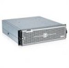
Dell™ PowerVault™ MD1000 Storage Enclosure Hardware Owner's Manual www.dell.com | support.dell.com - Dell PowerVault MD1000 | Hardware Owners Manual - Page 2
loss of data and tells you how to avoid the problem. CAUTION: A CAUTION indicates a potential for property damage, personal injury, or death. Information in this document is subject to change without notice. © 2005-2007 Dell Inc. All rights reserved. Reproduction in any manner whatsoever without - Dell PowerVault MD1000 | Hardware Owners Manual - Page 3
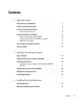
EMMs are Installed 16 EMM Thermal Shutdown 17 Power Supply and Cooling Fan Features 17 Enclosure Alarms 18 2 Operating Your Storage Enclosure Before You Begin 19 Cabling Your Enclosure for Unified or Split Mode 19 Connecting the Enclosure 20 Using Your Enclosure to Expand a Dell PowerVault - Dell PowerVault MD1000 | Hardware Owners Manual - Page 4
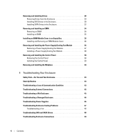
43 Troubleshooting External Connections 45 Troubleshooting a Wet Enclosure 45 Troubleshooting a Damaged Enclosure 46 Troubleshooting Power Supplies 46 Troubleshooting Enclosure Cooling Problems 47 Troubleshooting a Fan 48 Troubleshooting SAS and SATA Drives 48 Troubleshooting Enclosure - Dell PowerVault MD1000 | Hardware Owners Manual - Page 5
5 Getting Help Technical Assistance 51 Online Services 51 AutoTech Service 52 Automated Order-Status Service 52 Technical Support Service 52 Dell Enterprise Training and Certification 53 Problems With Your Order 53 Product Information 53 Returning Items for Warranty Repair or Credit 53 - Dell PowerVault MD1000 | Hardware Owners Manual - Page 6
6 Contents - Dell PowerVault MD1000 | Hardware Owners Manual - Page 7
information to configure and install these options. • RAID controller documentation. • Updates are sometimes included with the enclosure to describe changes to the enclosure, software, and/or documentation. NOTE: Always check for updates on support.dell.com and read the updates first because - Dell PowerVault MD1000 | Hardware Owners Manual - Page 8
indicated by the lights on the bezel. For information on installing and removing the bezel, see "Removing and Replacing the Front Bezel one power supply is supplying power to the enclosure. 3 Enclosure status (blue/amber) Steady amber: Power is on and enclosure is in reset state Steady blue: Power - Dell PowerVault MD1000 | Hardware Owners Manual - Page 9
Features 2 3 1 4 5 6 1 enclosure status LED 2 drive activity LED 3 drive status LED 7 4 power LED 5 split mode LED 6 enclosure mode switch 7 drives (15) Table 1-2. Front-Panel Components Component Icon Enclosure status LED (blue/amber) Condition Steady amber: Power is on and enclosure is - Dell PowerVault MD1000 | Hardware Owners Manual - Page 10
Changing the switch setting after power on will have no effect on enclosure configuration until the system is power cycled. Drive Carrier LED Indicators Each drive carrier in your enclosure has two LEDs: an activity LED (green) and a bi-color (green/amber) status LED (see Figure 1-3). The activity - Dell PowerVault MD1000 | Hardware Owners Manual - Page 11
Amber On 3000 ms Off 3000 ms Drive being spun down by user request or other nonfailure condition Back-Panel Indicators and Features Figure 1-4 shows the back-panel features of a fully populated enclosure containing both enclosure management modules (EMMs) and two power supply/cooling fan modules - Dell PowerVault MD1000 | Hardware Owners Manual - Page 12
fan modules (2) Enclosure Management Module (EMM) Each EMM provides data path and enclosure management functions for your enclosure, including: • Monitoring and controlling enclosure environment elements (temperature, fans, power supplies, and enclosure LEDs) • Controlling access to the drives - Dell PowerVault MD1000 | Hardware Owners Manual - Page 13
Panel 1 2 3 45 6 Table 1-4. EMM Component Functions Item Component Icon 1 Debug Port 2 SAS Port (In) In 3 In Port Link Status LED (green/amber) 4 SAS Port (Out) Out 5 Out Port Link Status LED (green/amber) Function Dell factory use only. Provide SAS connection for cabling to host or - Dell PowerVault MD1000 | Hardware Owners Manual - Page 14
(left) EMM. The remaining drives (slots 0-6) are controlled by the secondary (right) EMM. You must select either mode using the enclosure mode switch on the front panel of the enclosure before powering on (see Figure 1-7). NOTE: Clustering is not supported in the MD1000 host-based RAID solution - Dell PowerVault MD1000 | Hardware Owners Manual - Page 15
Figure 1-6. Drive Slot Distribution in Split Mode vs. Unified Mode EMM Control in Split Mode EMM Control in Unified Mode About Your System 15 - Dell PowerVault MD1000 | Hardware Owners Manual - Page 16
the audible alarm, enclosure LEDs, power supplies, and fans. Failover does not include providing connectivity to the drives controlled by the failed EMM. When a failed EMM is replaced, enclosure management functions do not automatically return to the replaced EMM unless an additional failure occurs - Dell PowerVault MD1000 | Hardware Owners Manual - Page 17
automatically via either a thermal shutdown command issued by the EMM firmware or via a command from Server Administrator. Power Supply and Cooling Fan Features Your storage enclosure supports two integrated, hot-pluggable power supply/cooling fan modules. Each module contains two separate cooling - Dell PowerVault MD1000 | Hardware Owners Manual - Page 18
the alarm, you must change the default setting in Server Administrator. For more information, see Server Administrator Storage Management Service documentation. Table 1-6. Critical and Noncritical Events Critical Events Two or more fan blowers have failed or a power supply/cooling fan module - Dell PowerVault MD1000 | Hardware Owners Manual - Page 19
that came with your storage enclosure, including: - Power cord - SAS interconnect cables - Documentation CD - Rail kit • Any relevant documentation, including: - Getting Started Guide - Rack Installation Guide or Rack Installation Instructions - Product Information Guide (for important safety - Dell PowerVault MD1000 | Hardware Owners Manual - Page 20
instructions and supported operating systems, see your Server Administrator documentation. 2 Turn off the host system and all attached devices. 3 Connect the external SAS cable(s) to the EMM SAS connector on the storage enclosure (see Figure 1-5 and Figure 2-1) and to the RAID controller - Dell PowerVault MD1000 | Hardware Owners Manual - Page 21
all power supply/cooling fan modules (see Figure 1-8). 7 Turn on power to the host system. 8 Check the LED indicators on the front and back of the storage enclosure. If any amber fault indicators are illuminated, see "Troubleshooting Your Enclosure." Using Your Enclosure to Expand a Dell PowerVault - Dell PowerVault MD1000 | Hardware Owners Manual - Page 22
the SAS 5/E adapter driver and firmware. For Windows hosts, use the update package. For Linux hosts, use the DKMS package. b Upgrade the Modular Disk Storage Manager on each host server. (The latest version is available from support.dell.com.) Refer to the PowerVault MD3000 Installation Guide for - Dell PowerVault MD1000 | Hardware Owners Manual - Page 23
: a Upgrade the SAS 5/E adapter driver and firmware. For Windows hosts, use the update package. For Linux hosts, use the DKMS package. b Upgrade the MD Storage Manager on each host (the latest version is available from support.dell.com). Refer to the PowerVault MD3000 Installation Guide for detailed - Dell PowerVault MD1000 | Hardware Owners Manual - Page 24
Turn off the MD3000 enclosure. 7 Connect the MD1000 expansion enclosure(s) to the MD3000 enclosure, as shown in the Dell PowerVault Compatibility Matrix (available from support.dell.com). 8 Power on the systems in the following order: a Turn on the MD1000 expansion enclosure or enclosures. Wait for - Dell PowerVault MD1000 | Hardware Owners Manual - Page 25
run diagnostics and perform firmware downloads to the enclosure. For more information, see the Server Assistant documentation for more details. Downloading Firmware You can download firmware updates for your storage enclosure using a Dell Update Package available at support.dell.com. NOTE: Firmware - Dell PowerVault MD1000 | Hardware Owners Manual - Page 26
26 Operating Your Storage Enclosure - Dell PowerVault MD1000 | Hardware Owners Manual - Page 27
and drive carriers • EMMs • Power supplies • Control panel • Enclosure midplane Recommended Tools The procedures in this section require the use of one or more of the following tools: • #2 Phillips-head screwdriver • Torx T10 driver • Wrist grounding strap, as explained in the safety instructions - Dell PowerVault MD1000 | Hardware Owners Manual - Page 28
Drives Your enclosure supports up to 15 SAS or SATA 3.0-Gbps drives, each one contained in its individual drive carrier. Each drive is hot-pluggable, allowing you to remove and insert drives without shutting down your enclosure. This section describes how to remove and install drives in your storage - Dell PowerVault MD1000 | Hardware Owners Manual - Page 29
will result in serious damage to the unseated drive carrier. NOTICE: To avoid data loss when removing a drive, Dell recommends that you use Server Administrator to prepare the drive for removal. See your Server Administrator documentation for more information. CAUTION: Always wear a wrist grounding - Dell PowerVault MD1000 | Hardware Owners Manual - Page 30
into the carrier: 1 If you are replacing a SAS drive in the carrier, remove the four screws that secure the drive to its carrier and remove the drive (see Figure 3-3). 2 Position the replacement drive into the drive carrier with the drive's controller board facing the carrier shield as shown in - Dell PowerVault MD1000 | Hardware Owners Manual - Page 31
drive carrier guide rail with the appropriate drive slot keying feature on the chassis face plate, and insert the drive (see Figure 3-2). 6 Push the drive the drive is inserted properly. If the indicator is not illuminated, see "Troubleshooting SAS and SATA Drives." As the drive rebuilds, the drive - Dell PowerVault MD1000 | Hardware Owners Manual - Page 32
static-sensitive components. Perform the following steps to install the new SATA drive into the carrier: 1 If you are replacing a drive in the carrier, remove the interposer, unclipping it from the carrier. Remove the four screws that secure the drive to its carrier and remove the drive (see Figure - Dell PowerVault MD1000 | Hardware Owners Manual - Page 33
the Drive in the Carrier 2 1 4 3 1 screws (4) 2 physical disk carrier 3 physical disk 4 interposer 5 With the drive carrier handle open, carefully align the channel on the drive carrier guide rail with the appropriate drive slot keying feature on the chassis face plate, and insert the drive (see - Dell PowerVault MD1000 | Hardware Owners Manual - Page 34
while performing the following procedures. See your Product Information Guide for safety information. Removing an EMM NOTICE: If you remove an EMM from an enclosure operating in split mode while connected to a host server, you will lose connection to the drives attached to the removed EMM. 1 Push - Dell PowerVault MD1000 | Hardware Owners Manual - Page 35
at support.dell.com for the latest information on firmware updates. NOTE: If you have two EMMs installed, both must be running the same firmware level. For information on updating firmware, see "Downloading Firmware." For information on EMM connections and cabling, see "Operating Your Storage - Dell PowerVault MD1000 | Hardware Owners Manual - Page 36
the cover out of the EMM bay. Figure 3-6. Removing and Installing an EMM Module Cover Removing and Installing the Power Supply/Cooling Fan Module Your enclosure supports two separate modules containing an integrated power supply and two cooling fans. While the enclosure can operate temporarily - Dell PowerVault MD1000 | Hardware Owners Manual - Page 37
the power supply you intend to remove using the on/off switch. 2 Unplug the AC power cable. 3 Using a Phillips-head screwdriver, loosen the two captive screws securing the power supply/cooling fan module in the bay (see Figure 3-7). Figure 3-7. Replacing the Power Supply 4 3 1 2 1 power supply - Dell PowerVault MD1000 | Hardware Owners Manual - Page 38
screws to secure the new power supply/cooling fan module in the bay. 4 Connect the AC power cable to the new power supply and to an electrical outlet. 5 Turn on the on/off switch on the new power supply. Removing and Installing the Control Panel The control panel powers the LED indicators on the - Dell PowerVault MD1000 | Hardware Owners Manual - Page 39
3-8). Also, make sure the guide tab on the control panel is fully inserted into the mounting slot on the backplane. 3 Replace the front faceplate and re-attach the 16 screws that hold it in place. 4 Re-install any drives you removed (see "Removing and Installing Drives"). 5 Push the enclosure all - Dell PowerVault MD1000 | Hardware Owners Manual - Page 40
Information Guide for complete information about safety precautions, working inside the enclosure and protecting against electrostatic discharge. The enclosure midplane contains the connectors for the drives, EMMs, control panel, and power supply/cooling modules. 1 Complete the "Removing the Control - Dell PowerVault MD1000 | Hardware Owners Manual - Page 41
5 Slide the EMM/power supply cage out of the enclosure and place it aside. 6 Reaching into the enclosure chassis from the back, carefully disconnect the midplane from the control panel and lift it out of the enclosure. (See Figure 3-10.) 7 To re-install the midplane, reverse the previous steps. - Dell PowerVault MD1000 | Hardware Owners Manual - Page 42
44 Installing Enclosure Components - Dell PowerVault MD1000 | Hardware Owners Manual - Page 43
loss of communication to occur: • Installing or replacing an EMM while the server is online • Downloading enclosure firmware • Disconnecting the cables to the enclosure or EMM while the server is online • Powering down the enclosure while the server is online Troubleshooting Your Enclosure 43 - Dell PowerVault MD1000 | Hardware Owners Manual - Page 44
5/E Adapter should recover without any additional user intervention or warning/error messages. Problem • Warning Messages During POST: - Foreign Configuration - Failed Virtual Disks Action • Foreign Configuration 1 Enter the Ctrl-R utility 2 Import the foreign configuration (right click "controller - Dell PowerVault MD1000 | Hardware Owners Manual - Page 45
the configuration information. NOTE: Do not initialize the new virtual disks. 6 Exit the Ctrl-R utility and boot to the operating system. For more information on the Ctrl-R utility, see the Dell PERC5/E Adapter User's Guide. Troubleshooting External Connections Loose or improperly connected cables - Dell PowerVault MD1000 | Hardware Owners Manual - Page 46
) • Power supply/cooling fan modules • EMMs • Enclosure midplane 2 Ensure that all cables are properly connected and that there are no bent pins in the connector. 3 Run any diagnostics available in Server Administrator. If the tests fail, see "Getting Help." Troubleshooting Power Supplies Problem - Dell PowerVault MD1000 | Hardware Owners Manual - Page 47
several seconds for the enclosure to recognize the power supply and to determine if it is working properly. 4 If the problem persists, see "Getting Help." Troubleshooting Enclosure Cooling Problems Problem • Systems management software issues a fan-related error message. Action Ensure that none of - Dell PowerVault MD1000 | Hardware Owners Manual - Page 48
diagnostic test from Server Administrator. 2 Locate the malfunctioning fan. 3 Ensure that the faulty power supply/cooling fan module is properly connected to the enclosure midplane. 4 If the problem persists, see "Getting Help." Troubleshooting SAS and SATA Drives CAUTION: Only trained service - Dell PowerVault MD1000 | Hardware Owners Manual - Page 49
, see "Getting Help." Problem • Multiple drives are not seen in the PERC 5/E Ctrl-R BIOS utility or Server Administrator Storage Management Service. Action 1 Verify that the EMM port link status LED and the EMM status LED are solid green for each port that is connected to a cable. If they are not - Dell PowerVault MD1000 | Hardware Owners Manual - Page 50
50 Troubleshooting Your Enclosure - Dell PowerVault MD1000 | Hardware Owners Manual - Page 51
assistance with a technical problem, perform the following steps: 1 Complete the procedures in "Troubleshooting Your Enclosure." 2 Run the enclosure diagnostics and record any information provided. 3 Use Dell's extensive suite of online services available at Dell Support at support.dell.com for help - Dell PowerVault MD1000 | Hardware Owners Manual - Page 52
FTP) ftp.dell.com/ Log in as user:anonymous, and use your e-mail address as your password. • Electronic Support Service [email protected] [email protected] (Asian/Pacific countries only) support.jp.dell.com (Japan only) support.euro.dell.com (Europe only) • Electronic Quote Service [email protected] - Dell PowerVault MD1000 | Hardware Owners Manual - Page 53
. 3 Include a copy of any diagnostic information indicating the tests you have run and any error messages reported by the system diagnostics. 4 Include any accessories that belong with the item(s) being returned (such as power cables, media such as CDs and diskettes, and guides) if the return is for - Dell PowerVault MD1000 | Hardware Owners Manual - Page 54
, or try other troubleshooting steps possible only at the enclosure itself. Ensure that the system documentation is available. CAUTION: Before servicing any components inside your computer, see your Product Information Guide for important safety information. Contacting Dell For customers in the - Dell PowerVault MD1000 | Hardware Owners Manual - Page 55
U.S. application - Software designed to help you perform a specific task or series of tasks. Applications run from the operating a drive. The modules are mounted into a chassis that includes power supplies and fans. BMC - Baseboard management controller. boot routine - A program that clears all - Dell PowerVault MD1000 | Hardware Owners Manual - Page 56
memory. EMC - Electromagnetic compatibility. EMI - Electromagnetic interference. EMM - Enclosure Management Module. ERA - Embedded remote access. ERA allows you to perform remote, or "out-of-band," server management on your network server using a remote access controller. ESD - Electrostatic - Dell PowerVault MD1000 | Hardware Owners Manual - Page 57
a peripheral device. (Drive controller subsystems include integrated host adapter circuitry.) To add a SCSI expansion bus to your system, you must install or connect the appropriate host adapter. hot-pluggable - The ability to remove a system component or attached device without powering down the - Dell PowerVault MD1000 | Hardware Owners Manual - Page 58
for implementing shared storage on a network. NAS systems have their own operating systems, integrated hardware, and software that are optimized to serve specific storage needs. NIC - Network interface controller. A device that is installed or integrated in a system to allow connection to a network - Dell PowerVault MD1000 | Hardware Owners Manual - Page 59
in protected mode. MS-DOS cannot run in protected mode. PS/2 - Personal System/2. PXE - Preboot eXecution Environment. A way of booting a system via a LAN (without a drive or bootable diskette). RAC - Remote access controller. RAID - Redundant array of independent disks. A method of providing data - Dell PowerVault MD1000 | Hardware Owners Manual - Page 60
system used to identify it when you call Dell for technical support. simple disk volume - The volume of free space on a single dynamic, physical disk. SMART - Self-Monitoring Analysis and Reporting Technology. Allows drives to report errors and failures to the system BIOS and then display an error - Dell PowerVault MD1000 | Hardware Owners Manual - Page 61
failure. USB - Universal Serial Bus. A USB connector provides a single connection point for multiple USB-compliant devices, such as mice and keyboards. USB devices can be connected and disconnected while the system is running. utility - A program used to manage system resources- memory, disk drives - Dell PowerVault MD1000 | Hardware Owners Manual - Page 62
62 Glossary - Dell PowerVault MD1000 | Hardware Owners Manual - Page 63
, 9 M Managing, 25 midplane cage, 40 installing and replacing, 40 P phone numbers, 54 power supplies troubleshooting, 46 power supply features, 17 R rack-mounted systems installing, 19 H hard drives installing and removing, 30 removing and replacing, 29 S safety, 43 support contacting Dell, 54 - Dell PowerVault MD1000 | Hardware Owners Manual - Page 64
T telephone numbers, 54 thermal thresholds, 17 tools needed, 27 troubleshooting, 43 cooling fan, 48 damaged system, 46 external connections, 45 hard drive, 48 power supplies, 46 start-up routine, 43 system cooling, 47 wet system, 45 W warranty, 7 64 Index
-
 1
1 -
 2
2 -
 3
3 -
 4
4 -
 5
5 -
 6
6 -
 7
7 -
8
-
9
-
10
-
11
-
12
-
13
-
14
-
15
-
16
-
17
-
18
-
19
-
20
-
21
-
22
-
23
-
24
-
25
-
26
-
27
-
28
-
29
-
30
-
31
-
32
-
33
-
34
-
35
-
36
-
37
-
38
-
39
-
40
-
41
-
42
-
43
-
44
-
45
-
46
-
47
-
48
-
49
-
50
-
51
-
52
-
53
-
54
-
55
-
56
-
57
-
58
-
59
-
60
-
61
-
62
-
63
-
64
 |
 |

www.dell.com | support.dell.com
Dell™ PowerVault™ MD1000
Storage Enclosure
Hardware Owner’s Manual