Dell PowerVault MD1000 Hardware Owners Manual - Page 12
Enclosure Management Module (EMM), Three LEDs In Port Link, Out Port Link, and EMM Status - power supply
 |
View all Dell PowerVault MD1000 manuals
Add to My Manuals
Save this manual to your list of manuals |
Page 12 highlights
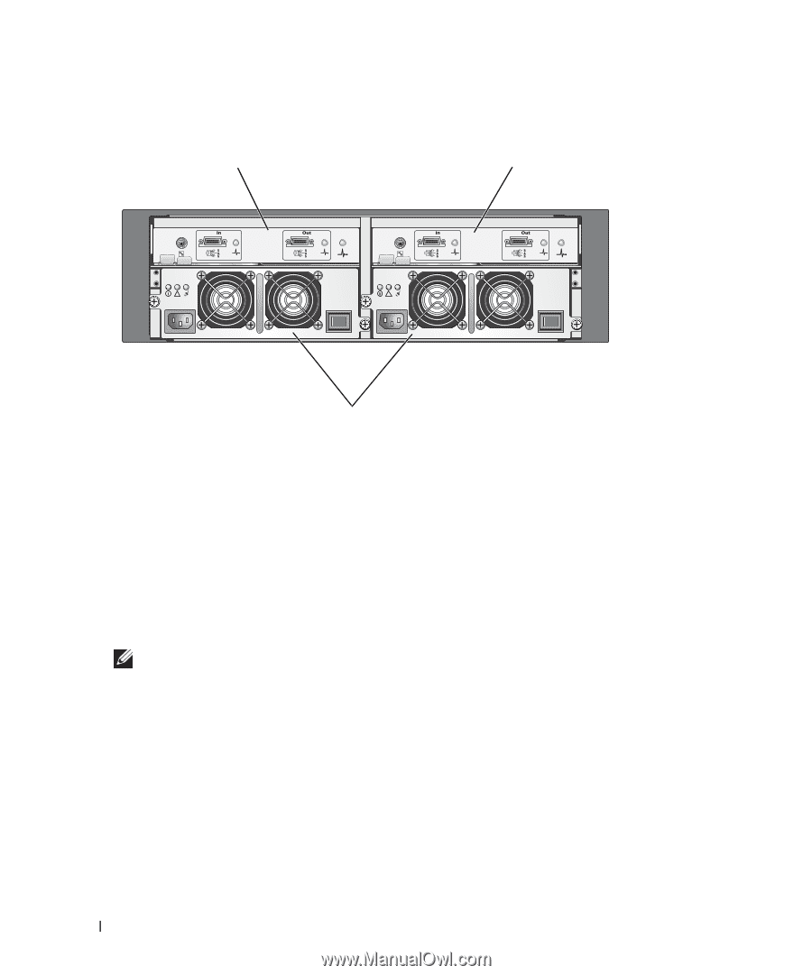
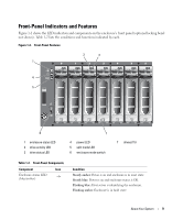
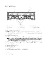
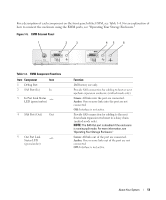
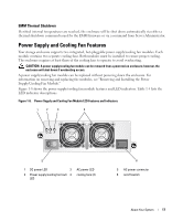
Figure 1-4. Back-Panel Features 1 2 3 1 primary EMM 2 secondary EMM 3 power supply/cooling fan modules (2) Enclosure Management Module (EMM) Each EMM provides data path and enclosure management functions for your enclosure, including: • Monitoring and controlling enclosure environment elements (temperature, fans, power supplies, and enclosure LEDs) • Controlling access to the drives • Communicating enclosure attributes and states to the host server NOTE: At least one EMM must be installed in the enclosure. If only one EMM is installed, it must be in the primary EMM bay (see Figure 1-4) and a blank module cover must be installed in the secondary EMM bay (see "Installing an EMM Module Cover in an Empty Bay"). Figure 1-5 shows a single EMM as it appears from the rear of the enclosure. The EMM connects to the enclosure via the enclosure midplane (see "Removing and Installing an EMM"). EMM connectors and components are shown in Figure 1-5 and include: • Debug port (Dell use only) • SAS port connector (In) • SAS port connector (Out) • Three LEDs (In Port Link, Out Port Link, and EMM Status) 12 About Your System
-
 1
1 -
2
-
3
-
4
-
5
-
6
-
 7
7 -
 8
8 -
 9
9 -
 10
10 -
 11
11 -
 12
12 -
 13
13 -
 14
14 -
 15
15 -
 16
16 -
 17
17 -
18
-
19
-
20
-
21
-
22
-
23
-
24
-
25
-
26
-
27
-
28
-
29
-
30
-
31
-
32
-
33
-
34
-
35
-
36
-
37
-
38
-
39
-
40
-
41
-
42
-
43
-
44
-
45
-
46
-
47
-
48
-
49
-
50
-
51
-
52
-
53
-
54
-
55
-
56
-
57
-
58
-
59
-
60
-
61
-
62
-
63
-
64
 |
 |