Dell PowerVault MD1000 Hardware Owners Manual - Page 38
Installing a Power Supply/Cooling Fan Module, Removing and Installing the Control Panel - connectivity
 |
View all Dell PowerVault MD1000 manuals
Add to My Manuals
Save this manual to your list of manuals |
Page 38 highlights
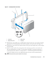
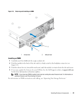
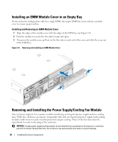
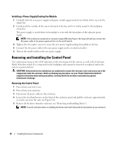
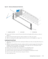
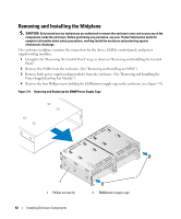
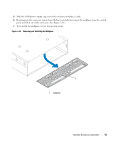
Installing a Power Supply/Cooling Fan Module 1 Carefully slide the new power supply/cooling fan module approximately two-thirds of the way into the empty bay. 2 Gently push the module all the way to the back of the bay until it is firmly seated in the backplane connector. The power supply is seated when its front plate is even with the front plate of the adjacent power supply. NOTE: If the enclosure is powered on, all power supply LEDs (see Figure 1-8) remain off until you connect the AC power cable to the power supply and turn on the on/off switch. 3 Tighten the two captive screws to secure the new power supply/cooling fan module in the bay. 4 Connect the AC power cable to the new power supply and to an electrical outlet. 5 Turn on the on/off switch on the new power supply. Removing and Installing the Control Panel The control panel powers the LED indicators on the front panel of the system, as well as the Enclosure Mode Selection switch. It is connected to the backplane and cannot be removed or replaced unless the system is powered down. CAUTION: Only trained service technicians are authorized to remove the enclosure cover and access any of the components inside the enclosure. Before performing any procedure, see your Product Information Guide for complete information about safety precautions, working inside the enclosure and protecting against electrostatic discharge. Removing the Control Panel 1 Power down your host server. 2 Power down your enclosure. 3 Disconnect all power cables to the enclosure. 4 Loosen the two thumbscrews on the front of the enclosure panel and pull the enclosure approximately six inches out from the rack (see Figure 3-8). 5 Remove all the drives from the enclosure (see "Removing and Installing Drives"). NOTE: To avoid confusion when re-installing the drives, mark each drive with its slot position as you remove it. 40 Installing Enclosure Components
-
 1
1 -
2
-
3
-
4
-
5
-
6
-
7
-
8
-
9
-
10
-
11
-
12
-
13
-
14
-
15
-
16
-
17
-
18
-
19
-
20
-
21
-
22
-
23
-
24
-
25
-
26
-
27
-
28
-
29
-
30
-
31
-
32
-
 33
33 -
 34
34 -
 35
35 -
 36
36 -
 37
37 -
 38
38 -
 39
39 -
 40
40 -
 41
41 -
 42
42 -
 43
43 -
44
-
45
-
46
-
47
-
48
-
49
-
50
-
51
-
52
-
53
-
54
-
55
-
56
-
57
-
58
-
59
-
60
-
61
-
62
-
63
-
64
 |
 |