Dell PowerVault NX200 Hardware Owner's Manual - Page 112
Internal USB Memory Keys, System Setup program.
 |
View all Dell PowerVault NX200 manuals
Add to My Manuals
Save this manual to your list of manuals |
Page 112 highlights
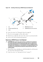
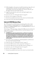
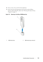
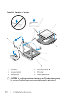
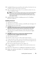
3 Pull back slightly on the retention standoff tab at the front edge of the card and gently lift the card off the retention standoff. See Figure 3-16. As the holder releases from the standoff, the connector under the card disengages from the system board connector. 4 Angle the card so that the notch on the card slips through the clip on the system board. 5 Close the system. See "Closing the System" on page 80. 6 Place the system upright on a flat surface. 7 Reattach any peripherals and connect the system to an electrical outlet. 8 Turn on the system and attached peripherals. Internal USB Memory Keys The USB memory key installed inside your system can be used as a boot device, security key, or mass storage device. The USB connector must be enabled by the Internal USB Port option in the Integrated Devices screen of the System Setup program. To boot from a USB memory key, configure the USB memory key with a boot image and then specify the USB memory key in the boot sequence in the System Setup program. CAUTION: Many repairs may only be done by a certified service technician. You should only perform troubleshooting and simple repairs as authorized in your product documentation, or as directed by the online or telephone service and support team. Damage due to servicing that is not authorized by Dell is not covered by your warranty. Read and follow the safety instructions that came with the product. 1 Turn off the system, including any attached peripherals, and disconnect the system from the electrical outlet. 2 Open the system. See "Opening the System" on page 79. 3 Locate the USB connector on the system board. See Figure 6-1. 4 Insert the USB memory key into the USB connector. See Figure 3-17. 5 Close the system. See "Closing the System" on page 80. 6 Place the system upright on a flat surface. 7 Reattach any peripherals and connect the system to an electrical outlet. 110 Installing System Components
-
 1
1 -
2
-
3
-
4
-
5
-
6
-
7
-
8
-
9
-
10
-
11
-
12
-
13
-
14
-
15
-
16
-
17
-
18
-
19
-
20
-
21
-
22
-
23
-
24
-
25
-
26
-
27
-
28
-
29
-
30
-
31
-
32
-
33
-
34
-
35
-
36
-
37
-
38
-
39
-
40
-
41
-
42
-
43
-
44
-
45
-
46
-
47
-
48
-
49
-
50
-
51
-
52
-
53
-
54
-
55
-
56
-
57
-
58
-
59
-
60
-
61
-
62
-
63
-
64
-
65
-
66
-
67
-
68
-
69
-
70
-
71
-
72
-
73
-
74
-
75
-
76
-
77
-
78
-
79
-
80
-
81
-
82
-
83
-
84
-
85
-
86
-
87
-
88
-
89
-
90
-
91
-
92
-
93
-
94
-
95
-
96
-
97
-
98
-
99
-
100
-
101
-
102
-
103
-
104
-
105
-
106
-
 107
107 -
 108
108 -
 109
109 -
 110
110 -
 111
111 -
 112
112 -
 113
113 -
 114
114 -
 115
115 -
 116
116 -
 117
117 -
118
-
119
-
120
-
121
-
122
-
123
-
124
-
125
-
126
-
127
-
128
-
129
-
130
-
131
-
132
-
133
-
134
-
135
-
136
-
137
-
138
-
139
-
140
-
141
-
142
-
143
-
144
-
145
-
146
-
147
-
148
-
149
-
150
-
151
-
152
-
153
-
154
-
155
-
156
-
157
-
158
-
159
-
160
-
161
-
162
-
163
-
164
-
165
-
166
 |
 |
