Denon D-F100MC Owners Manual - Page 6
Connections
 |
View all Denon D-F100MC manuals
Add to My Manuals
Save this manual to your list of manuals |
Page 6 highlights
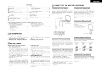
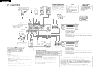
ENGLISH 4 CONNECTIONS LD player, video deck, etc. FM antenna AM loop antenna Speaker systems Connecting the speaker systems Connect the speaker system for the left channel (the left side as seen from the front) to the "L" terminals, the speaker system for the right channel to the "R" terminals. Be sure to use speaker systems with an impedance of 4 Ω/ohms or greater. CAUTION: Whenever the power switch is in the STANDBY position, the unit is still connected on AC line voltage. Please be sure to unplug the cord when you leave home for, say, a vacation. PRECAUTIONS FOR INSTALLATION For heat dispersal, leave at least 10 cm of space between the top, back and sides of this unit and the wall or other components. Right AM-FM Stereo Receiver (DRA-F100) • Disconnect the ground cord if humming or noise is produced when it is connected. Ground cord Record player SIGNAL GND L FM COAX 75º LOOP AM ANT. R PHONO AUX CD PB-TAPE-REC PB-MD-REC L SYSTEM CONNECTOR 12 R R L IMPEDANCE 4~16º SPEAKERS Power plug Left AC 120 V 60 Hz (Plug into a power outlet) Stacking installation B REMOTE SENSOR SYSTEM ON / STANDBY PERSONAL COMPONENT SYSTEM / AM-FM STEREO RECEIVER DRA-F100 EON-TA EON-PTY RT TIMER TUNED STEREO AUTO PHONES TUNING DOWN UP BAND MONO / STEREO BASS TIMER DISPLAY MEMORY FUNCTION MHz TREBLE CH BALANCE L R B OPEN/CLOSE ON / STANDBY PERSONAL COMPONENT SYSTEM / COMPACT DISC PLAYER DCD-F100 VOLUME 3 / / AC OUTLET 120V 60Hz SWITCHED 120W(1A.)MAX OPTICAL RL OUTPUT RL INPUT B REMOTE SENSOR PICK REC MODE ON / STANDBY EJECT INPUT SELECT DIGITAL ANALOG 12 PERSONAL COMPONENT SYSTEM / MINIDISC RECORDER DMD-F100 POWER LOADING MECHANISM RANDOM D.IN 1 04Tr L dB -60 -40 -30 R 12m -20 -12 -6 -2 48s 0 OVER MD recorder 1 3 REC / PICK REC CD SRS PUSH ENTER CHARACTER EDIT - + REC LEVEL Connecting a MD recorder Connections for recording: Connect the tape deck's recording input jacks (LINE IN or REC) to this unit's tape recording (OUT) jacks using pin plug cords. Connections for playback: Connect the tape deck's playback output jacks (LINE OUT or PB) to this unit's tape playback (IN) jacks using pin plug cords. Tape deck Use a record player with an MM cartridge. NOTE: This system includes digital circuitry which may cause interference such as color blotching or changes in the color on TVs. If this happens, move the system and the TV as far apart as possible. LINE OUT L R CD player (DCD-F100) SYSTEM CONNECTOR 12 OPTICAL DIGITAL OUT AC OUTLET 120V 60Hz UNSWITCHED 120W(1A.)MAX RL OUTPUT RL INPUT Note to CATV system installer: This reminder is provided to call the CATV system installer's attention to Article 820-40 of the NEC which provides guidelines for proper grounding and, in B OPEN / CLOSE ON / STANDBY REV. MODE PERSONAL COMPONENT SYSTEM / STEREO CASSETTE TAPE DECK DRR-F100 TAPE dB -40 -30 -20 -10 -5 -3 -1 0 +1 +3 +5 -10 L R B PLAY REC/ REC MUTE CD SRS REC LEVEL COUNTER RESET DOLBY NR MIN MAX Connecting a tape deck Connections for recording: Connect the tape deck's recording input jacks (LINE IN or REC) to this unit's tape recording (REC) jacks using pin plug cords. Connections for playback: Connect the tape deck's playback output jacks (LINE OUT or PB) to this unit's tape playback AC Outlets • SWITCHED outlet (DRA-F100) particular, specifies that the cable ground shall be connected to the grounding system of the building, as close to the point of cable entry as practical. (PB) jacks using pin plug cords. The power of this outlet is switched on and off by the receiver's SYSTEM power operation switch. This outlet will also be switched on when the power is set to ONSTANDBY with the remote control. When the receiver is in the standby mode, the outlet switches off after approximately 20 seconds. • UNSWITCHED outlets (DCD-F100) These outlets remains on at all times, regardless of the setting of the CD player's and cassette's power operation switch. System operations Such system operations as the timer and the auto on functions, as well as remote control operations cannot be performed unless all the RCA pin-plug cords and system connector cords are connected between the units, so be sure to make all the connections properly as shown in the diagram. Also, disconnecting system connectors while the system is operating may result in malfunction. Be sure to unplug the power cord before changing connections. NOTES: • Do not plug the power cord into the power outlet until all connections are completed. Be sure to interconnect the channels (L to L (white) and R to R (red)) properly, as shown on the diagram. • Insert the plugs securely. Incomplete connections may result in noise. • Be sure to connect the speaker cords between the speaker terminals and the speaker systems with the same polarities (+ to +, - to -). If the polarities are switched, the sound at the center will be weak, the position of the different instruments will be unclear, and the stereo effect will be lost. • After unplugging the power cord, wait about 5 seconds before plugging it back in. ✽ Do not connect the receiver's AC cord to the outlets on the CD player 6 (DCD-F100). Doing so could result in damage. • Note that setting the connection cords (pin-plug cords) next to the power cords may result in humming or other noise.
-
 1
1 -
 2
2 -
 3
3 -
 4
4 -
 5
5 -
 6
6 -
 7
7 -
 8
8 -
 9
9 -
 10
10 -
 11
11 -
 12
12 -
13
-
14
-
15
-
16
-
17
-
18
-
19
-
20
-
21
-
22
-
23
-
24
-
25
-
26
-
27
-
28
-
29
-
30
-
31
-
32
-
33
-
34
-
35
-
36
-
37
-
38
-
39
-
40
-
41
-
42
-
43
-
44
-
45
-
46
-
47
-
48
-
49
-
50
-
51
-
52
-
53
-
54
 |
 |
