Electrolux CEI30EF5GS Service Manual - Page 10
Electronic Surface Element Control, Esec 30 Troubleshooting Guide, Iq Touch Models
 |
View all Electrolux CEI30EF5GS manuals
Add to My Manuals
Save this manual to your list of manuals |
Page 10 highlights
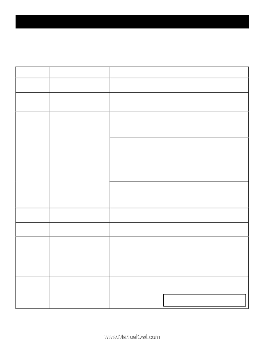
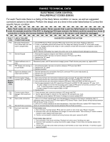
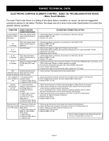
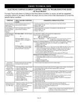
RANGE TECHNICAL DATA ELECTRONIC SURFACE ELEMENT CONTROL (ESEC 30) TROUBLESHOOTING GUIDE - IQ Touch Models - For each Fault code there is a listing of the likely failure condition or cause, as well as suggested corrective actions to be taken. Perform the steps one at a time in the order listed below to correct the specific failure condition. SYMPTOM LIKELY FAILURE CONDITION/ CAUSE SUGGESTED CORRECTIVE ACTION Control Beeping & ESEC key display ribbon cable is Center Burner Only disconnected or defective LED's Flashing 1. Check/reseat ribbon connection J3 connection on the ESEC 30 UIB. 2. Replace ESEC 30 UIB. 3. Replace TST panel. Control Beeping & Left Side Burners Only LED's Flashing ESEC key display ribbon cable is disconnected or defective 1. Check/reseat ribbon connection J2 connection on the ESEC30 UIB. 2. Replace ESEC 30 UIB. 3. Replace TST panel. Control Beeping & All Burners LED's Flashing E11 Failure Mode - Shorted Keypad or E14 Failure Mode - ESEC key read ribbon cable is unplugged or defective or E15 Failure Mode - Internal ESEC error or Signal loss between ESEC 30 UIB and ESEC relay board. Turn off power to range for 30 seconds then reapply power. Does error return within 5 seconds ? YES: Go to Solution A NO: Does error return after 30 seconds? YES: Go to Solution B NO: Test operation. If error does not return then the condition was corrected by power reset. Solution A - E14 Failure Mode key read ribbon cable is disconnected or defective 1. Check/reseat ribbon connection J4 connection on the ESEC 30 UIB. 2. Replace ESEC 30 UIB. 3. Replace TST panel. E15 Failure Mode ESEC error or signal loss between ESEC 30 UIB and relay board. 1. Check harness and connections between connector P6 of ESEC30 UIB to connector J2 of ESEC relay board. Repair or replace harness as needed. 2. If connection and harness are good. then replace ESEC relay board. 3. If error remains replace ESEC30 UIB. 4. If the previous steps do not resolve the failure replace the TST panel. Solution B - E11 Failure Mode Shorted Keypad 1. Reset power supply to range to see if failure code will clear. 2. Check/reseat ribbon harness and connectors between the TST panel and ESEC 30 UIB. 3. Replace the TST panel 4. Replace the ESEC 30 UIB "hot surface" displayed and no power to Element Surface element and its associated hot surface limiter mis-wired 1. Correct wiring of that element and its hot surface limiter. "hot surface" displayed when surface is cold 1. Hot surface limiter contacts closed. 1. Disconnect power and check continuity of hot surface limiter contacts. (See Note A) 2. Defective Relay Board. 2. If hot surface limiter contacts are open replace ESEC relay board. 3. Defective ESEC 30 UIB 3. Replace ESEC 30 UIB Surface Element hot, but "hot surface" is not displayed 1. Loose connection between surface element and Relay Board J4 2. Miswired element harness. 3. Open limiter contacts. 4. Failed harness or connector from UIB to Relay Board 5. Defective Relay Board. 6 Defective ESEC 30 UIB 1. Check the wire harness connector and seat properly to Relay Board J4 connector. 2. Check surface harness for correct wiring from each element's hot surface limiter - correct wiring or replace harness if necessary. 3. Turn on all elements to Hi. Wait 3 minutes to ensure all surfaces are hot. Check continuity of limiter switch circuit for each element. (See Note A) 4. Check the wire harness and connectors from ESEC 30 UIB P5 to Relay Board Connector J5. Replace harness if defective. 5. Replace Relay Board 6. Replace ESEC 30 UIB Element does not heat when turned on at TST panel. 1. Miswiring or faulty connection from element to Relay Board 2. Faulty connection from ESEC 30 UIB to ESEC Relay Board 3. Open Element 4. Defective Relay Board 5. Defective UIB 1. Check wiring harness and connections from element to Relay Board. 2. Check harness and connections from UIB connector P10 to Relay Board J3. 3. Check continuity of surface element heating circuit. 4. Replace ESEC Relay Board. 5. Replace ESEC 30 UIB Note A: Limiter contacts can be tested through the harness on Relay Board connector J4 Page 10
-
 1
1 -
2
-
3
-
4
-
 5
5 -
 6
6 -
 7
7 -
 8
8 -
 9
9 -
 10
10 -
 11
11 -
 12
12 -
 13
13 -
 14
14 -
 15
15 -
16
-
17
-
18
-
19
-
20
-
21
-
22
-
23
-
24
-
25
-
26
-
27
-
28
-
29
-
30
-
31
-
32
-
33
-
34
-
35
-
36
-
37
-
38
-
39
-
40
-
41
-
42
-
43
-
44
-
45
-
46
-
47
 |
 |