Electrolux CEI30EF5GS Service Manual - Page 22
between the EOC and Oven Relay Board.
 |
View all Electrolux CEI30EF5GS manuals
Add to My Manuals
Save this manual to your list of manuals |
Page 22 highlights
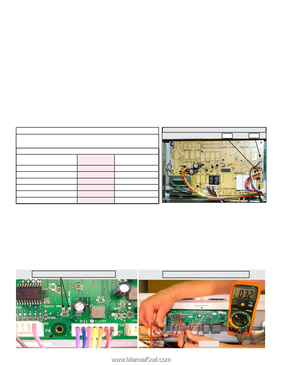
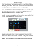
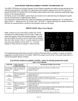
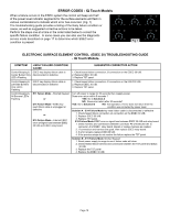
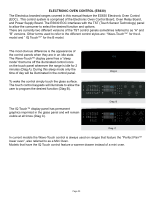
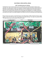
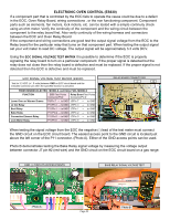
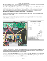
ELECTRONIC oven CONTROL (ES630) If a component part that is controlled by the EOC fails to operate the cause could be due to a defect in the EOC, Oven Relay Board, wiring connections , or the non functioning component. Component parts such as elements, fan motors, lock motors, etc. can be tested with a simple continuity check using an ohm meter. Verify the continuity of the component and the wiring circuit between the component to the relay board first. Also verify continuity of the wiring harness and connectors between the EOC and Oven Relay Board. If the component and wiring connections are good test the output signal voltage from the EOC to the Relay board for the particular relay that turns on that component part. When testing the output signal set your volt meter to read DC voltage. The output signal will be approximately 3.3 volts DCV. Using the EOC SIGNAL VOLTAGE TEST MATRIX it is possible to determine if the EOC is properly signaling the relay board to turn on a particular component. If the proper signal is detected but the relay does not close then the relay board is defective and must be replaced. If the proper signal is not detected then the EOC is defective and must be replaced. EOC Signal Voltage Test Matrix (ES630) Test for 3.3 VDC (+/- .5 volts) between GND on EOC circuit board and the indicated connector pin when the specified function is activated. FREESTANDING ELECTRIC MODELS, and DUAL FUEL MODELS FUNCTION EOC Test Points Relay Board Test Points Connector/Pin# Connector/Pin # Lower Oven or Warmer Drawer P9/Pin 7 → to GND J5/Pin 7 → to GND L2 Out Relay P11/Pin 4 → to GND J7/Pin 4 → to GND Broil Relay P11/Pin 1 → to GND J7/Pin 1 → to GND Bake Relay P11/ Pin 2 → to GND J7/Pin 2 → to GND Convection Element Relay P11/Pin 5 → to GND J7/Pin 5 → to GND Lock Motor Relay P11/Pin 6 → to GND J7/Pin 6 → to GND RELAY BOARD CONNECTORS J7 J5 When testing the signal voltage from the EOC the negative (-) lead of the test meter must connect the GND circuit on the EOC circuit board. The easiest access point to the GND circuit is located just above the left corner of the P11 connector. (Photo A). Either of the GND access points can be used. Photo B demonstrates testing the Bake Relay signal voltage by measuring the voltage output between connector J7 pin #2 (red wire) and the GND circuit on the EOC circuit board on a gas range. GND (-) CIRCUIT ACCESS POINTS BAKE RELAY SIGNAL VOLTAGE TEST Photo A Page 22 Photo B
-
 1
1 -
2
-
3
-
4
-
5
-
6
-
7
-
8
-
9
-
10
-
11
-
12
-
13
-
14
-
15
-
16
-
 17
17 -
 18
18 -
 19
19 -
 20
20 -
 21
21 -
 22
22 -
 23
23 -
 24
24 -
 25
25 -
 26
26 -
 27
27 -
28
-
29
-
30
-
31
-
32
-
33
-
34
-
35
-
36
-
37
-
38
-
39
-
40
-
41
-
42
-
43
-
44
-
45
-
46
-
47
 |
 |