Electrolux CEI30EF5GS Service Manual - Page 37
Convection Fan Blade and Element Replacement
 |
View all Electrolux CEI30EF5GS manuals
Add to My Manuals
Save this manual to your list of manuals |
Page 37 highlights
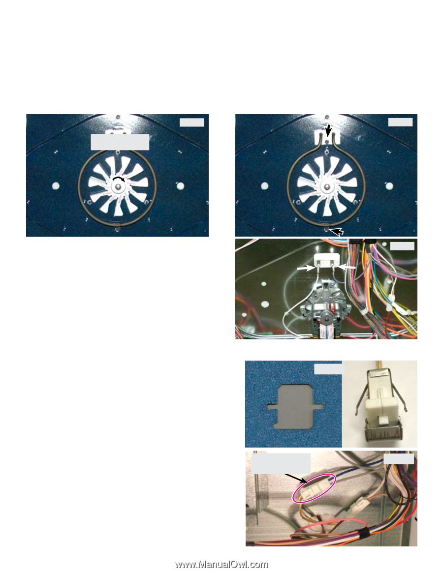
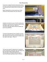
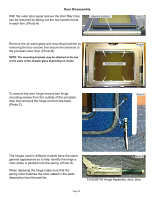
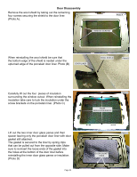
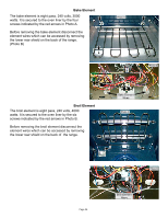
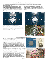
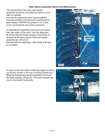
Convection Fan Blade and Element Replacement The Convection Fan Blade and Element are concealed by the fan cover. Remove the cover as described on page 35. The Blade can be removed by using a 13mm The convection element is a single pass, 120 socket wrench to remove the blade retaining volts, 350 watts. It is secured to the oven liner nut. The nut has left hand threads so to remove by the two screws indicated by the red arrows in the nut turn the wrench in a clockwise direction. Photo B. (Photo A) Photo A Photo B Turn Nut Clockwise To Remove Before removing the convection element disconnect the element wires which can be accessed by removing the lower rear shield on the back of the range. (Photo C) Photo C Rack Sensing Switch Replacement The rack sensing switch is installed into a cutout in the oven liner rear wall. (Photo D) To replace the switch first turn off the power to the range and remove the lower back cover panel. Unplug the harness connector (Photo E) and tie a 36 inch length of strong string or cord to the end of the connector that is attached to the switch. Secure the other end of the string so that it can not pull all the way through. From inside the oven remove the rack sensor assembly by taking out the two screws at the top and bottom of the assembly. (Page 26 - Photo A). Depress the tabs on the switch (Photo D) to release it from the cutout and carefully pull the switch with the attached wire harness inside the oven cavity. Attach the string to the new switch harness and carefully pull the harness back through the oven liner and insulation . Page 37 Rack Switch Harness Connector Photo D Photo E
-
 1
1 -
2
-
3
-
4
-
5
-
6
-
7
-
8
-
9
-
10
-
11
-
12
-
13
-
14
-
15
-
16
-
17
-
18
-
19
-
20
-
21
-
22
-
23
-
24
-
25
-
26
-
27
-
28
-
29
-
30
-
31
-
 32
32 -
 33
33 -
 34
34 -
 35
35 -
 36
36 -
 37
37 -
 38
38 -
 39
39 -
 40
40 -
 41
41 -
 42
42 -
43
-
44
-
45
-
46
-
47
 |
 |