Electrolux CEI30EF5GS Service Manual - Page 23
Power Supply Boards
 |
View all Electrolux CEI30EF5GS manuals
Add to My Manuals
Save this manual to your list of manuals |
Page 23 highlights
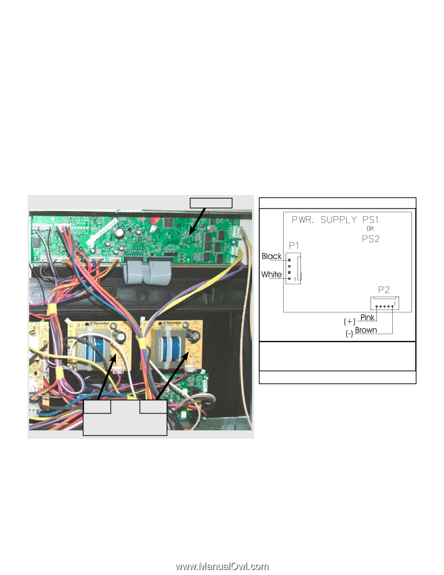
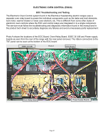
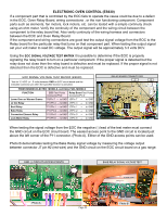
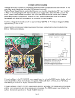
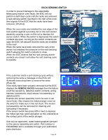
Power Supply Boards The EOC and ESEC system are powered by separate power supply boards that are mounted on the rear of the range chassis just below the EOC as seen in photo A. The two Power Supply Boards are identical however one board is designated as PS 1 and the other is PS 2 on the wiring diagram. PS 2 provides the power supply to the EOC while PS 1 powers the ESEC system. Wire harness connections and colors are identical on both boards and it does not matter which board is connected to the EOC or ESEC system however the length of the wiring harness will only allow both harnesses to be connected in one orientation. Incoming voltage to the boards should be approximately 120 VAC at P1. Output voltage should be approximately 8 VDC at P2. Always test the incoming and outgoing voltage at the power supply boards when troubleshooting EOC or ESEC control failures. Photo A EOC Board Power Supply Board PS 2 PS 1 Power Supply Boards Power Supply Board (PS1 or PS2) Test Points Connector P1 pins 1 & 4 - 120 vac Connector P2 pins 1 & 5 - 8 vdc NOTE: All voltages are approximate. If there is a failure in the PS 1 (ESEC) power supply board or wiring the ESEC system display will not illuminate and the surface elements can not operate. Additionally there will likely be an F20 failure code displayed on the EOC display after several seconds. If there is a failure in the PS 2 (EOC) power supply board or wiring the EOC display will not illuminate and the oven components and other devices can not operate. The ESEC system may still allow the surface elements to operate even though the EOC does not . Page 23
-
 1
1 -
2
-
3
-
4
-
5
-
6
-
7
-
8
-
9
-
10
-
11
-
12
-
13
-
14
-
15
-
16
-
17
-
 18
18 -
 19
19 -
 20
20 -
 21
21 -
 22
22 -
 23
23 -
 24
24 -
 25
25 -
 26
26 -
 27
27 -
 28
28 -
29
-
30
-
31
-
32
-
33
-
34
-
35
-
36
-
37
-
38
-
39
-
40
-
41
-
42
-
43
-
44
-
45
-
46
-
47
 |
 |