Electrolux CEI30EF5GS Service Manual - Page 43
Lower Oven Chassis
 |
View all Electrolux CEI30EF5GS manuals
Add to My Manuals
Save this manual to your list of manuals |
Page 43 highlights
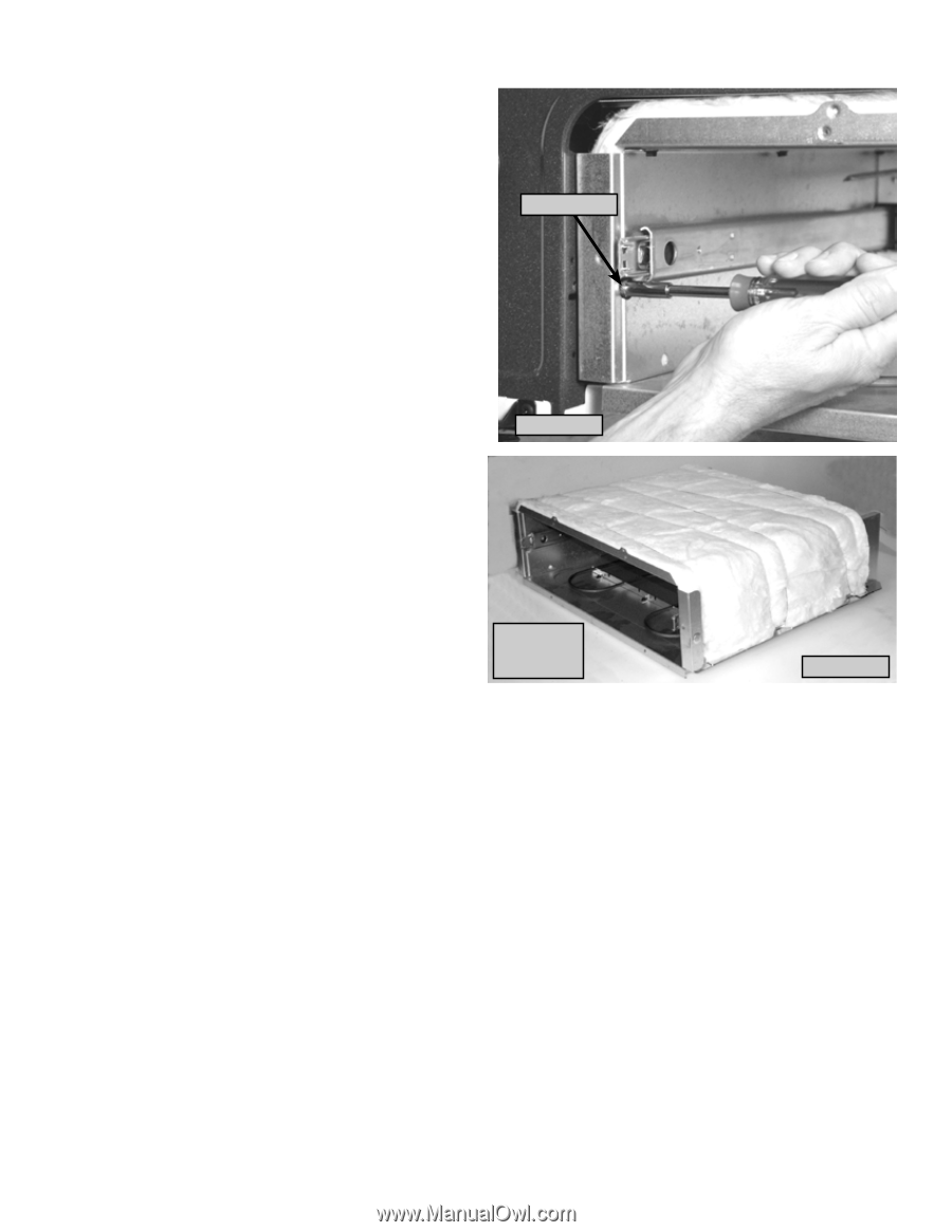
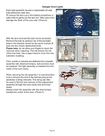
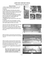
Lower Oven Chassis The lower oven chassis can be removed as an entire assembly. Begin by disconnecting the wire harness connections to the element and cavity light. Remove the drawer per instructions on page 41. Screw Access Using a ¼" nut driver with magnetic screw holder remove the two screws securing the lower oven chassis to the range chassis. These screws are accessed through the holes in the lower oven cavity liner just below the drawer glide rail. (Photo A). Photo A The lower oven chassis can now be pulled forward and removed from the range. (Photo B). With the lower oven chassis removed the insulation and chassis panels can be serviced. NOTE: The lower oven chassis is not available as a complete replacement assembly. Lower Oven Chassis Assembly Photo B Page 43
-
 1
1 -
2
-
3
-
4
-
5
-
6
-
7
-
8
-
9
-
10
-
11
-
12
-
13
-
14
-
15
-
16
-
17
-
18
-
19
-
20
-
21
-
22
-
23
-
24
-
25
-
26
-
27
-
28
-
29
-
30
-
31
-
32
-
33
-
34
-
35
-
36
-
37
-
 38
38 -
 39
39 -
 40
40 -
 41
41 -
 42
42 -
 43
43 -
 44
44 -
 45
45 -
 46
46 -
 47
47
 |
 |