Fluke 225C Service Manual - Page 27
Introduction, 2 Equipment Required For Verification, 3 General Instructions - oscilloscope
 |
View all Fluke 225C manuals
Add to My Manuals
Save this manual to your list of manuals |
Page 27 highlights
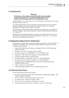
4 Performance Verification 4.1 Introduction 4.1 Introduction Warning Procedures in this chapter should be performed by qualified service personnel only. To avoid electrical shock, do not perform any servicing unless you are qualified to do so. The ScopeMeter® test tool (referred to as test tool) should be calibrated and in operating condition when you receive it. The following performance tests are provided to ensure that the test tool is in a proper operating condition. If the test tool fails any of the performance tests, calibration adjustment (see Chapter 5) and/or repair is necessary. The Performance Verification Procedure is based on the specifications, see Chapter 2 of this Service Manual. The values given here are valid for ambient temperatures between 18 °C and 28 °C. The Performance Verification Procedure is a quick way to check most of the test tool's specifications. Because of the highly integrated design of the test tool, it is not always necessary to check all features separately. 4.2 Equipment Required For Verification The primary source instrument used in the verification procedures is the Fluke 5500A. If a 5500A is not available, you can substitute another calibrator as long as it meets the minimum test requirements. • Fluke 5500A Multi Product Calibrator, including SC300 or SC600 Oscilloscope Calibration Option. • Stackable Test Leads (4x), supplied with the 5500A. • 50Ω Coax Cables (2x), Fluke PM9091 (1.5m) or PM9092 (0.5m). • Male BNC to Dual Female BNC adapter (1x), Fluke PM9093/001 • 50Ω feed through termination, Fluke PM9585. • Dual Banana Plug to Female BNC Adapter (1x), Fluke PM9081/001. • Dual Banana Jack to Male BNC Adapter (1x), Fluke PM9082/001. • TV Signal Generator, Philips PM5418, NOT required if SC600 Oscilloscope Calibration Option is used. • 75Ω Coax cable (1x), Fluke PM9075. • 75Ω Feed through termination (1x), ITT-Pomona model 4119-75. 4.3 General Instructions Follow these general instructions for all tests: • For all tests, power the test tool with the BC190 power adapter/battery charger. The battery pack must be installed. • Allow the 5500A to satisfy its specified warm-up period. • For each test point , wait for the 5500A to settle. • Allow the test tool a minimum of 30 minutes to warm up. • One division on the LCD consists of 25 pixels ( 1 pixel = 0.04 division). 4-3
-
 1
1 -
2
-
3
-
4
-
5
-
6
-
7
-
8
-
9
-
10
-
11
-
12
-
13
-
14
-
15
-
16
-
17
-
18
-
19
-
20
-
21
-
 22
22 -
 23
23 -
 24
24 -
 25
25 -
 26
26 -
 27
27 -
 28
28 -
 29
29 -
 30
30 -
 31
31 -
 32
32 -
33
-
34
-
35
-
36
-
37
-
38
-
39
-
40
-
41
-
42
-
43
-
44
-
45
-
46
-
47
-
48
-
49
-
50
-
51
-
52
-
53
-
54
-
55
-
56
-
57
-
58
-
59
-
60
-
61
-
62
-
63
-
64
-
65
-
66
-
67
-
68
-
69
-
70
-
71
-
72
-
73
-
74
-
75
-
76
-
77
-
78
-
79
-
80
-
81
-
82
-
83
-
84
-
85
-
86
 |
 |
