Fujitsu 4860C Operator's Guide - Page 145
Replacing the Pick Roller Unit, Please refer to the Setup Mode Details
 |
View all Fujitsu 4860C manuals
Add to My Manuals
Save this manual to your list of manuals |
Page 145 highlights
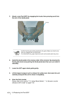
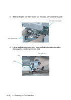
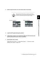
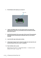
4. Install a new Pick roller unit in the reverse order of its removal. When attaching the Pick roller unit, hold the unit as shown. HINT Engage the drive ring onto the drive shaft. Move left and align the clutch ring with the shaft and move right to engage. 4 Incorrect installation Correct installation REPLACEMENT OF CONSUMABLES 5. Lower the ADF upper sheet guide carefully. 6. Lift the Upper transport unit to release the safety lock, then lower the unit carefully and push the unit to close it completely. 7. Clear the Pick roller counter. Please refer to the section "7.3 Setup Mode Details", " 9. Abrasion counter (Abrasion CNT) reset " on page 7-33. 4.4 Replacing the Pick Roller Unit 4-11
-
 1
1 -
2
-
3
-
4
-
5
-
6
-
7
-
8
-
9
-
10
-
11
-
12
-
13
-
14
-
15
-
16
-
17
-
18
-
19
-
20
-
21
-
22
-
23
-
24
-
25
-
26
-
27
-
28
-
29
-
30
-
31
-
32
-
33
-
34
-
35
-
36
-
37
-
38
-
39
-
40
-
41
-
42
-
43
-
44
-
45
-
46
-
47
-
48
-
49
-
50
-
51
-
52
-
53
-
54
-
55
-
56
-
57
-
58
-
59
-
60
-
61
-
62
-
63
-
64
-
65
-
66
-
67
-
68
-
69
-
70
-
71
-
72
-
73
-
74
-
75
-
76
-
77
-
78
-
79
-
80
-
81
-
82
-
83
-
84
-
85
-
86
-
87
-
88
-
89
-
90
-
91
-
92
-
93
-
94
-
95
-
96
-
97
-
98
-
99
-
100
-
101
-
102
-
103
-
104
-
105
-
106
-
107
-
108
-
109
-
110
-
111
-
112
-
113
-
114
-
115
-
116
-
117
-
118
-
119
-
120
-
121
-
122
-
123
-
124
-
125
-
126
-
127
-
128
-
129
-
130
-
131
-
132
-
133
-
134
-
135
-
136
-
137
-
138
-
139
-
 140
140 -
 141
141 -
 142
142 -
 143
143 -
 144
144 -
 145
145 -
 146
146 -
 147
147 -
 148
148 -
 149
149 -
 150
150 -
151
-
152
-
153
-
154
-
155
-
156
-
157
-
158
-
159
-
160
-
161
-
162
-
163
-
164
-
165
-
166
-
167
-
168
-
169
-
170
-
171
-
172
-
173
-
174
-
175
-
176
-
177
-
178
-
179
-
180
-
181
-
182
-
183
-
184
-
185
-
186
-
187
-
188
-
189
-
190
-
191
-
192
-
193
-
194
-
195
-
196
-
197
-
198
-
199
-
200
-
201
-
202
-
203
-
204
-
205
-
206
-
207
-
208
-
209
-
210
-
211
-
212
-
213
-
214
-
215
-
216
-
217
-
218
-
219
-
220
-
221
-
222
-
223
-
224
-
225
-
226
-
227
-
228
-
229
-
230
-
231
-
232
-
233
-
234
-
235
-
236
-
237
-
238
-
239
-
240
-
241
-
242
-
243
-
244
-
245
-
246
-
247
-
248
-
249
-
250
-
251
-
252
-
253
-
254
-
255
-
256
-
257
-
258
-
259
-
260
-
261
-
262
-
263
-
264
-
265
-
266
-
267
-
268
-
269
-
270
-
271
-
272
-
273
-
274
-
275
-
276
-
277
-
278
-
279
-
280
-
281
-
282
-
283
-
284
-
285
-
286
-
287
-
288
-
289
-
290
-
291
-
292
-
293
-
294
-
295
-
296
-
297
-
298
-
299
-
300
-
301
-
302
-
303
-
304
-
305
-
306
-
307
-
308
-
309
-
310
-
311
-
312
-
313
-
314
-
315
-
316
 |
 |
4-11
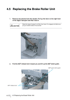
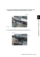
4.4 Replacing the Pick Roller Unit
4
REPLACEMENT OF CONSUMABLES
4.
Install a new Pick roller unit in the reverse order of its removal.
5.
Lower the ADF upper sheet guide carefully.
6.
Lift the Upper transport unit to release the safety lock, then lower the unit
carefully and push the unit to close it completely.
7.
Clear the Pick roller counter.
Please refer to the section “7.3
Setup Mode Details”, “
9. Abrasion counter
(Abrasion CNT) reset ” on page 7-33.
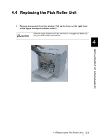
HINT
When attaching the Pick roller unit, hold the unit as shown.
Engage the drive ring onto the drive shaft. Move left and align
the clutch ring with the shaft and move right to engage.
Incorrect installation
Correct installation