Fujitsu MHT2030AT Manual/User Guide - Page 135
Idle X'97' Or X'e3, X'fe' To X'ff']
 |
UPC - 683728090579
View all Fujitsu MHT2030AT manuals
Add to My Manuals
Save this manual to your list of manuals |
Page 135 highlights
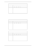
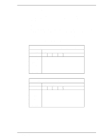
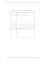
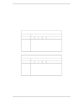
5.3 Host Commands (23) IDLE (X'97' or X'E3') Upon receipt of this command, the device sets the BSY bit of the Status register, and enters the idle mode. Then, the device clears the BSY bit, and generates an interrupt. The device generates interrupt even if the device has not fully entered the idle mode. If the spindle of the device is already rotating, the spin-up sequence shall not be implemented. By using this command, the APS (Automatic Power Standby) timer function is enabled and the timer immediately starts the countdown. When the timer reaches the specified value, the device enters standby mode. The APS timer is set to prohibition if the Sector Count register's value was "00h" when device has received this command. The APS timer allows the device to change to the standby mode automatically after specified period. When the device enters the state which is waiting Host Command, the timer starts countdown. If any command is not issued while the timer is counting down, the device automatically enters the standby mode. If any command is issued while the timer is counting down, the timer is initialized and the command is executed. The timer restarts countdown after completion of the command execution. The period of timer count is set depending on the value of the Sector Count register as shown below. Sector Count register value 0 1 to 240 [X'00'] [X'01' to X'F0'] 241 to 251 [X'F1' to X'FB'] 252 [X'FC'] 253 [X'FD'] 254 to 255 [X'FE' to X'FF'] Point of timer Timeout disabled (Value × 5) seconds ((Value-240) × 30) min 21 minutes 8 hrs 21 minutes 15 seconds At command issuance (I/O registers setting contents) 1F7H(CM) 1F6H(DH) 1F5H(CH) 1F4H(CL) 1F3H(SN) 1F2H(SC) 1F1H(FR) X'97' or X'E3' x x x xx xx xx Period of timer xx DV xx C141-E192-02EN 5-61
-
 1
1 -
2
-
3
-
4
-
5
-
6
-
7
-
8
-
9
-
10
-
11
-
12
-
13
-
14
-
15
-
16
-
17
-
18
-
19
-
20
-
21
-
22
-
23
-
24
-
25
-
26
-
27
-
28
-
29
-
30
-
31
-
32
-
33
-
34
-
35
-
36
-
37
-
38
-
39
-
40
-
41
-
42
-
43
-
44
-
45
-
46
-
47
-
48
-
49
-
50
-
51
-
52
-
53
-
54
-
55
-
56
-
57
-
58
-
59
-
60
-
61
-
62
-
63
-
64
-
65
-
66
-
67
-
68
-
69
-
70
-
71
-
72
-
73
-
74
-
75
-
76
-
77
-
78
-
79
-
80
-
81
-
82
-
83
-
84
-
85
-
86
-
87
-
88
-
89
-
90
-
91
-
92
-
93
-
94
-
95
-
96
-
97
-
98
-
99
-
100
-
101
-
102
-
103
-
104
-
105
-
106
-
107
-
108
-
109
-
110
-
111
-
112
-
113
-
114
-
115
-
116
-
117
-
118
-
119
-
120
-
121
-
122
-
123
-
124
-
125
-
126
-
127
-
128
-
129
-
 130
130 -
 131
131 -
 132
132 -
 133
133 -
 134
134 -
 135
135 -
 136
136 -
 137
137 -
 138
138 -
 139
139 -
 140
140 -
141
-
142
-
143
-
144
-
145
-
146
-
147
-
148
-
149
-
150
-
151
-
152
-
153
-
154
-
155
-
156
-
157
-
158
-
159
-
160
-
161
-
162
-
163
-
164
-
165
-
166
-
167
-
168
-
169
-
170
-
171
-
172
-
173
-
174
-
175
-
176
-
177
-
178
-
179
-
180
-
181
-
182
-
183
-
184
-
185
-
186
-
187
-
188
-
189
-
190
-
191
-
192
-
193
-
194
-
195
-
196
-
197
-
198
-
199
-
200
-
201
-
202
-
203
-
204
-
205
-
206
-
207
-
208
-
209
-
210
-
211
-
212
-
213
-
214
-
215
-
216
-
217
-
218
-
219
-
220
-
221
-
222
-
223
-
224
-
225
-
226
-
227
-
228
-
229
-
230
-
231
-
232
-
233
-
234
-
235
-
236
-
237
-
238
-
239
-
240
-
241
-
242
-
243
-
244
-
245
-
246
-
247
-
248
-
249
-
250
-
251
-
252
-
253
-
254
-
255
-
256
 |
 |
