Fujitsu MHT2030AT Manual/User Guide - Page 37
System Configuration, 2.2.1 ATA interface, 2.2.2 1 drive connection - connector
 |
UPC - 683728090579
View all Fujitsu MHT2030AT manuals
Add to My Manuals
Save this manual to your list of manuals |
Page 37 highlights
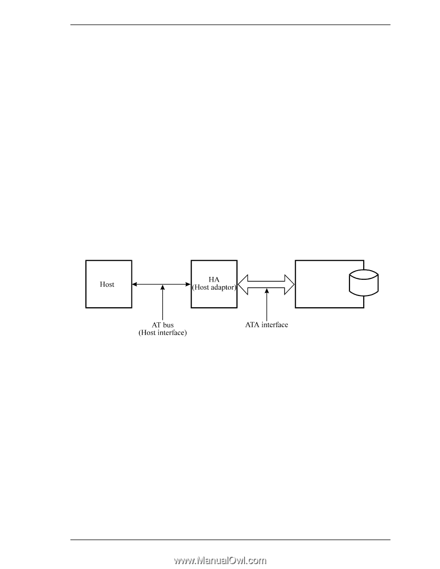
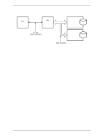
2.2 System Configuration (6) Read/write circuit The read/write circuit uses a LSI chip for the read/write preamplifier. It improves data reliability by preventing errors caused by external noise. (7) Controller circuit The controller circuit consists of an LSI chip to improve reliability. The highspeed microprocessor unit (MPU) achieves a high-performance AT controller. 2.2 System Configuration 2.2.1 ATA interface Figures 2.2 and 2.3 show the ATA interface system configuration. The drive has a 44pin PC AT interface connector and supports PIO mode 4 transfer at 16.6 MB/s, Multiword DMA mode 2 transfer at 16.6 MB/s and also U-DMA mode 5 (100 MB/s). 2.2.2 1 drive connection MHT2080AT MMHHTC22006302AATT MMHHTC22004400AATT MHT2030AT Figure 2.2 1 drive system configuration C141-E192-02EN 2-3
-
 1
1 -
2
-
3
-
4
-
5
-
6
-
7
-
8
-
9
-
10
-
11
-
12
-
13
-
14
-
15
-
16
-
17
-
18
-
19
-
20
-
21
-
22
-
23
-
24
-
25
-
26
-
27
-
28
-
29
-
30
-
31
-
 32
32 -
 33
33 -
 34
34 -
 35
35 -
 36
36 -
 37
37 -
 38
38 -
 39
39 -
 40
40 -
 41
41 -
 42
42 -
43
-
44
-
45
-
46
-
47
-
48
-
49
-
50
-
51
-
52
-
53
-
54
-
55
-
56
-
57
-
58
-
59
-
60
-
61
-
62
-
63
-
64
-
65
-
66
-
67
-
68
-
69
-
70
-
71
-
72
-
73
-
74
-
75
-
76
-
77
-
78
-
79
-
80
-
81
-
82
-
83
-
84
-
85
-
86
-
87
-
88
-
89
-
90
-
91
-
92
-
93
-
94
-
95
-
96
-
97
-
98
-
99
-
100
-
101
-
102
-
103
-
104
-
105
-
106
-
107
-
108
-
109
-
110
-
111
-
112
-
113
-
114
-
115
-
116
-
117
-
118
-
119
-
120
-
121
-
122
-
123
-
124
-
125
-
126
-
127
-
128
-
129
-
130
-
131
-
132
-
133
-
134
-
135
-
136
-
137
-
138
-
139
-
140
-
141
-
142
-
143
-
144
-
145
-
146
-
147
-
148
-
149
-
150
-
151
-
152
-
153
-
154
-
155
-
156
-
157
-
158
-
159
-
160
-
161
-
162
-
163
-
164
-
165
-
166
-
167
-
168
-
169
-
170
-
171
-
172
-
173
-
174
-
175
-
176
-
177
-
178
-
179
-
180
-
181
-
182
-
183
-
184
-
185
-
186
-
187
-
188
-
189
-
190
-
191
-
192
-
193
-
194
-
195
-
196
-
197
-
198
-
199
-
200
-
201
-
202
-
203
-
204
-
205
-
206
-
207
-
208
-
209
-
210
-
211
-
212
-
213
-
214
-
215
-
216
-
217
-
218
-
219
-
220
-
221
-
222
-
223
-
224
-
225
-
226
-
227
-
228
-
229
-
230
-
231
-
232
-
233
-
234
-
235
-
236
-
237
-
238
-
239
-
240
-
241
-
242
-
243
-
244
-
245
-
246
-
247
-
248
-
249
-
250
-
251
-
252
-
253
-
254
-
255
-
256
 |
 |