Fujitsu MHT2030AT Manual/User Guide - Page 55
Air filter, 4.3 Circuit Configuration
 |
UPC - 683728090579
View all Fujitsu MHT2030AT manuals
Add to My Manuals
Save this manual to your list of manuals |
Page 55 highlights
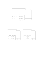
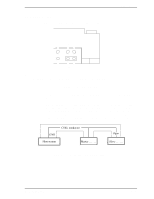
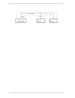
4.3 Circuit Configuration 4.2.4 Air filter There are two types of air filters: a breather filter and a circulation filter. The breather filter makes an air in and out of the DE to prevent unnecessary pressure around the spindle when the disk starts or stops rotating. When disk drives are transported under conditions where the air pressure changes a lot, filtered air is circulated in the DE. The circulation filter cleans out dust and dirt from inside the DE. The disk drive cycles air continuously through the circulation filter through an enclosed loop air cycle system operated by a blower on the rotating disk. 4.3 Circuit Configuration Figure 4.1 shows the power supply configuration of the disk drive, and Figure 4.2 shows the disk drive circuit configuration. (1) Read/write circuit The read/write circuit consists of two circuits; read/write preamplifier (PreAMP) and read channel (RDC). The PreAMP consists of the write current switch circuit, that flows the write current to the head coil, and the voltage amplifier circuit, that amplitudes the read output from the head. The RDC is the read demodulation circuit using the Modified Extended Partial Response (MEEPR), and contains the Viterbi detector, programmable filter, adaptable transversal filter, times base generator, data separator circuits, RLL (Run Length Limited) encoder and servo demodulation circuit. (2) Servo circuit The position and speed of the voice coil motor are controlled by 2 closed-loop servo using the servo information recorded on the data surface. The servo information is an analog signal converted to digital for processing by a MPU and then reconverted to an analog signal for control of the voice coil motor. The MPU precisely sets each head on the track according on the servo information on the media surface. (3) Spindle motor driver circuit The circuit measures the interval of a PHASE signal generated by counterelectromotive voltage of a motor and controls the motor speed comparing target speed. C141-E192-02EN 4-3
-
 1
1 -
2
-
3
-
4
-
5
-
6
-
7
-
8
-
9
-
10
-
11
-
12
-
13
-
14
-
15
-
16
-
17
-
18
-
19
-
20
-
21
-
22
-
23
-
24
-
25
-
26
-
27
-
28
-
29
-
30
-
31
-
32
-
33
-
34
-
35
-
36
-
37
-
38
-
39
-
40
-
41
-
42
-
43
-
44
-
45
-
46
-
47
-
48
-
49
-
 50
50 -
 51
51 -
 52
52 -
 53
53 -
 54
54 -
 55
55 -
 56
56 -
 57
57 -
 58
58 -
 59
59 -
 60
60 -
61
-
62
-
63
-
64
-
65
-
66
-
67
-
68
-
69
-
70
-
71
-
72
-
73
-
74
-
75
-
76
-
77
-
78
-
79
-
80
-
81
-
82
-
83
-
84
-
85
-
86
-
87
-
88
-
89
-
90
-
91
-
92
-
93
-
94
-
95
-
96
-
97
-
98
-
99
-
100
-
101
-
102
-
103
-
104
-
105
-
106
-
107
-
108
-
109
-
110
-
111
-
112
-
113
-
114
-
115
-
116
-
117
-
118
-
119
-
120
-
121
-
122
-
123
-
124
-
125
-
126
-
127
-
128
-
129
-
130
-
131
-
132
-
133
-
134
-
135
-
136
-
137
-
138
-
139
-
140
-
141
-
142
-
143
-
144
-
145
-
146
-
147
-
148
-
149
-
150
-
151
-
152
-
153
-
154
-
155
-
156
-
157
-
158
-
159
-
160
-
161
-
162
-
163
-
164
-
165
-
166
-
167
-
168
-
169
-
170
-
171
-
172
-
173
-
174
-
175
-
176
-
177
-
178
-
179
-
180
-
181
-
182
-
183
-
184
-
185
-
186
-
187
-
188
-
189
-
190
-
191
-
192
-
193
-
194
-
195
-
196
-
197
-
198
-
199
-
200
-
201
-
202
-
203
-
204
-
205
-
206
-
207
-
208
-
209
-
210
-
211
-
212
-
213
-
214
-
215
-
216
-
217
-
218
-
219
-
220
-
221
-
222
-
223
-
224
-
225
-
226
-
227
-
228
-
229
-
230
-
231
-
232
-
233
-
234
-
235
-
236
-
237
-
238
-
239
-
240
-
241
-
242
-
243
-
244
-
245
-
246
-
247
-
248
-
249
-
250
-
251
-
252
-
253
-
254
-
255
-
256
 |
 |
