Garmin G1000H Bell 407GX Cockpit Reference Guide - Page 24
Power Assurance Check, Dual Tachometer - installation manual
 |
View all Garmin G1000H manuals
Add to My Manuals
Save this manual to your list of manuals |
Page 24 highlights
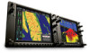
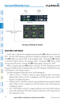
Engine Indication & Crew Alerting System Flight Instruments EICAS Nav/Com/ XPDR/Audio timer flashes beginning when 30 seconds remain until an exceedance will occur; the timer is automatically removed when either Q or MGT fall below takeoff limits. Dual Tachometer The dual tachometer displays rotor speed (NR) and power turbine speed (NP) in revolutions per minute (rpm). A readout for NR is provided. The long pointer represents NR along the gauge scale; NP is shown with the short pointer. A white tick mark represents the FADEC normal governing point. When Quiet Mode is active, a magenta reference bug is shown on the tachometer to indicate the Quiet Mode governing point. POWER ASSURANCE CHECK NOTE: Follow the procedures in the Rotorcraft Flight Manual (RFM) for configuring the helicopter for the power assurance check prior to activating the feature on the G1000H. AFCS GPS Nav Flight Planning Procedures Hazard Avoidance Additional Features Abnormal Operation 1) If the Particle Separator or Snow Baffle are installed, proceed to step 2. If neither are installed, proceed to step 7. 2) Turn the large FMS Knob to select the AUX Page group. 3) Turn the small FMS Knob to select System Setup. If necessary, press the SETUP 1 Softkey to display the System Setup 1 Page 4) Press the FMS Knob momentarily to activate the flashing cursor. 5) Turn the large FMS Knob to highlight the desired option field in the Inlet Box. 6) Turn the small FMS Knob one click to the right to select ON or one click to the left to select OFF. 7) Press the ENGINE Softkey to display the Engine Page. 8) Press the PWR CHK Softkey. When the power assurance check is activated a 'PWR CHECK' box is displayed containing a progress meter. If the helicopter configuration for the power assurance check is invalid, the error message 'CHK LIMITS' is displayed. Otherwise, the power assurance check will complete after ten seconds. Values that equal or exceed performance minimums will be displayed in white; values that do not meet performance minimums will be shown with yellow highlighted black readouts. Dashes are displayed if data used to perform the power assurance check is not available. 8 Garmin G1000H™ Cockpit Reference Guide for the Bell 407GX 190-01254-00 Rev. A Annun/ Alerts Appendix Index
-
 1
1 -
2
-
3
-
4
-
5
-
6
-
7
-
8
-
9
-
10
-
11
-
12
-
13
-
14
-
15
-
16
-
17
-
18
-
 19
19 -
 20
20 -
 21
21 -
 22
22 -
 23
23 -
 24
24 -
 25
25 -
 26
26 -
 27
27 -
 28
28 -
 29
29 -
30
-
31
-
32
-
33
-
34
-
35
-
36
-
37
-
38
-
39
-
40
-
41
-
42
-
43
-
44
-
45
-
46
-
47
-
48
-
49
-
50
-
51
-
52
-
53
-
54
-
55
-
56
-
57
-
58
-
59
-
60
-
61
-
62
-
63
-
64
-
65
-
66
-
67
-
68
-
69
-
70
-
71
-
72
-
73
-
74
-
75
-
76
-
77
-
78
-
79
-
80
-
81
-
82
-
83
-
84
-
85
-
86
-
87
-
88
-
89
-
90
-
91
-
92
-
93
-
94
-
95
-
96
-
97
-
98
-
99
-
100
-
101
-
102
-
103
-
104
-
105
-
106
-
107
-
108
-
109
-
110
-
111
-
112
-
113
-
114
-
115
-
116
-
117
-
118
-
119
-
120
-
121
-
122
-
123
-
124
-
125
-
126
-
127
-
128
-
129
-
130
-
131
-
132
-
133
-
134
-
135
-
136
 |
 |
