Hayward Variable Speed Pump Technical Guide - Page 10
Installation, Interface /Wall Mount
 |
View all Hayward Variable Speed Pump manuals
Add to My Manuals
Save this manual to your list of manuals |
Page 10 highlights
Installation-Interface /Wall Mount 4. The data cable needs to be routed through the second (low voltage) conduit opening (fig 15). 5. Remove the wall mounting data plug from the electrical compartment as shown (fig 16). 6. You will need to procure a six wire data cable, as short as possible, and attach the wires to the data plug as shown (fig 17) taking care to note the color and corresponding number next to the data plug (fig 15). Data cable is routed separate of high voltage and in it's own channel within the motor electrical compartment Data Plug Figure 15 Figure 16 Figure 17 Page 8
-
 1
1 -
2
-
3
-
4
-
 5
5 -
 6
6 -
 7
7 -
 8
8 -
 9
9 -
 10
10 -
 11
11 -
 12
12 -
 13
13 -
 14
14 -
 15
15 -
16
-
17
-
18
-
19
-
20
-
21
-
22
-
23
-
24
-
25
-
26
-
27
-
28
-
29
-
30
-
31
-
32
-
33
-
34
-
35
-
36
-
37
-
38
-
39
-
40
-
41
-
42
-
43
-
44
-
45
-
46
-
47
-
48
-
49
-
50
 |
 |

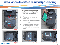
Installation
–
Interface /Wall Mount
4.
The data cable needs to be routed through the second
(low voltage)
conduit opening
(fig 15).
5.
Remove the wall mounting data plug from the electrical compartment as shown
(fig 16).
6.
You will need to procure a six wire data cable, as short as possible, and attach the wires to the data
plug as shown
(fig 17)
taking care to note the color and corresponding number next to the data plug
(fig
15).
Data Plug
Figure 15
Figure 16
Figure 17
Page 8
Data cable is
routed separate of
high voltage and
in it’s own
channel within the
motor electrical
compartment