Hayward Variable Speed Pump Technical Guide - Page 13
Installation, Relay Connected Controls
 |
View all Hayward Variable Speed Pump manuals
Add to My Manuals
Save this manual to your list of manuals |
Page 13 highlights
Installation-Relay Connected Controls (Non Hayward/Goldline compatible software & third party controls) 1. Pump power (230 VAC) needs to be brought into the "line in" contacts on the Filter Pump Relay from a breaker in the control box. The "Load Out" side will feed the incoming high voltage for the pump (fig 24). Cable used for data connections should be rated for maximum voltage in motor compartment. Filter Pump Replay AUX Relay AUX Relay AUX Relay Fig 24 Page 11
-
 1
1 -
2
-
3
-
4
-
5
-
6
-
7
-
 8
8 -
 9
9 -
 10
10 -
 11
11 -
 12
12 -
 13
13 -
 14
14 -
 15
15 -
 16
16 -
 17
17 -
 18
18 -
19
-
20
-
21
-
22
-
23
-
24
-
25
-
26
-
27
-
28
-
29
-
30
-
31
-
32
-
33
-
34
-
35
-
36
-
37
-
38
-
39
-
40
-
41
-
42
-
43
-
44
-
45
-
46
-
47
-
48
-
49
-
50
 |
 |

Page 11
Fig 24
Filter Pump Replay
AUX Relay
AUX Relay
AUX Relay
1.
Pump power
(230 VAC)
needs to be brought into the “line in” contacts on the Filter Pump Relay from a
breaker in the control box.
The “Load Out” side will feed the incoming high voltage for the pump
(fig
24)
.
Cable used for data connections should be rated for maximum voltage in motor compartment.
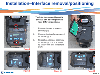
Installation
–
Relay Connected Controls
(Non Hayward/Goldline compatible software & third party controls)