Hayward Variable Speed Pump Technical Guide - Page 37
Remove the two screw as shown
 |
View all Hayward Variable Speed Pump manuals
Add to My Manuals
Save this manual to your list of manuals |
Page 37 highlights
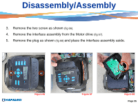
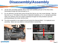
Disassembly/Assembly 3. Remove the two screw as shown (fig 66). 4. Remove the interface assembly from the Motor drive (fig 67). 5. Remove the plug as shown (fig 68) and place the interface assembly aside. Figure 66 Figure 67 Figure 68 Page 35
-
 1
1 -
2
-
3
-
4
-
5
-
6
-
7
-
8
-
9
-
10
-
11
-
12
-
13
-
14
-
15
-
16
-
17
-
18
-
19
-
20
-
21
-
22
-
23
-
24
-
25
-
26
-
27
-
28
-
29
-
30
-
31
-
 32
32 -
 33
33 -
 34
34 -
 35
35 -
 36
36 -
 37
37 -
 38
38 -
 39
39 -
 40
40 -
 41
41 -
 42
42 -
43
-
44
-
45
-
46
-
47
-
48
-
49
-
50
 |
 |

3.
Remove the two screw as shown
(fig 66).
4.
Remove the interface assembly from the Motor drive
(fig 67).
5.
Remove the plug as shown
(fig 68)
and place the interface assembly aside.
Disassembly/Assembly
Figure 67
Figure 68
Figure 66
Page 35