Hayward Variable Speed Pump Technical Guide - Page 12
Installation-Hayward/Goldline Controls - no display
 |
View all Hayward Variable Speed Pump manuals
Add to My Manuals
Save this manual to your list of manuals |
Page 12 highlights
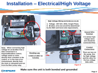
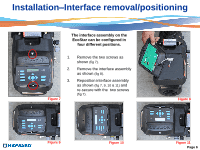
Installation-Hayward/Goldline Controls (Compatible software shown below) 1. Maximum 500‟ for data cable The data cable needs to be run through the second (data) conduit opening and channel (Page 8). 2. Remove the two data plugs (COMBUS & DISPLAY) from the wiring compartment (fig 23) and the 4 connector data plug from the controller (fig 22). Wire 7 on the pump to 2 on the controller, 8 on the pump to 3 on the controller and 1 on the pump to 4 to the controller as shown (fig 22 & 23). Reinstall plugs. Wire colors can be different as those shown as long as they match point to point. Note: When connecting high voltage for an EcoStar that is data connected to a Hayward/Goldline control, voltage needs to come directly from a breaker in the control, or in the case of an OnCommand, directly from the main or sub- panel and not from the filter pump relay. Control Data Plug Software versions necessary to operate the EcoStar Aqua Logic/Pro Logic/Aqua Plus v2.65 or higher OnCommand 1.00 or higher E-Command 4 (Original E-Command not compatible) v2.80 or higher 2 3 Figure 22 4 Note: Wire from 4 on Remote display to 1 on 7 EcoStar is not needed in units 8 Mfg 5/19/11 1 going forward Figure 23 Pump Terminal Data Plugs Page 10
-
 1
1 -
2
-
3
-
4
-
5
-
6
-
 7
7 -
 8
8 -
 9
9 -
 10
10 -
 11
11 -
 12
12 -
 13
13 -
 14
14 -
 15
15 -
 16
16 -
 17
17 -
18
-
19
-
20
-
21
-
22
-
23
-
24
-
25
-
26
-
27
-
28
-
29
-
30
-
31
-
32
-
33
-
34
-
35
-
36
-
37
-
38
-
39
-
40
-
41
-
42
-
43
-
44
-
45
-
46
-
47
-
48
-
49
-
50
 |
 |
