Hayward Variable Speed Pump Technical Guide - Page 11
Installation, Interface/Wall Mount
 |
View all Hayward Variable Speed Pump manuals
Add to My Manuals
Save this manual to your list of manuals |
Page 11 highlights
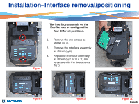
Installation-Interface/Wall Mount 7. Secure the wall mounting bracket and route the six wire data cable through the channel on the bottom of the bracket (fig 18). 8. Attach the six wires to the new data plug as shown, taking care to note the color and corresponding number on the data plug as you did with the data plug on the pump (fig 20). Install the plug into the interface assembly (fig 19). 9. Attach the interface assembly to the mounting bracket with the two screws provided (fig 21). Figure 18 Figure 19 Figure 20 Figure 21 Page 9
-
 1
1 -
2
-
3
-
4
-
5
-
 6
6 -
 7
7 -
 8
8 -
 9
9 -
 10
10 -
 11
11 -
 12
12 -
 13
13 -
 14
14 -
 15
15 -
 16
16 -
17
-
18
-
19
-
20
-
21
-
22
-
23
-
24
-
25
-
26
-
27
-
28
-
29
-
30
-
31
-
32
-
33
-
34
-
35
-
36
-
37
-
38
-
39
-
40
-
41
-
42
-
43
-
44
-
45
-
46
-
47
-
48
-
49
-
50
 |
 |

Installation
–
Interface/Wall Mount
7.
Secure the wall mounting bracket and route the six wire data cable through the channel on the bottom
of the bracket
(fig 18).
8.
Attach the six wires to the new data plug as shown, taking care to note the color and corresponding
number on the data plug as you did with the data plug on the pump
(fig 20).
Install the plug into the
interface assembly
(fig 19).
9.
Attach the interface assembly to the mounting bracket with the two screws provided
(fig 21).
Figure 18
Figure 19
Figure 20
Figure 21
Page 9