Hayward Variable Speed Pump Technical Guide - Page 39
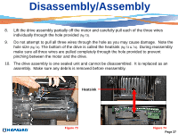
The drive assembly is one sealed unit and cannot be disassembled., It is replaced as an
 |
View all Hayward Variable Speed Pump manuals
Add to My Manuals
Save this manual to your list of manuals |
Page 39 highlights
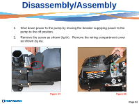
Disassembly/Assembly 8. Lift the drive assembly partially off the motor and carefully pull each of the three wires individually through the hole provided (fig 73). 9. Do not attempt to pull all three wires through the hole as you may cause damage. Note the hole size (fig 74). The bottom of the drive is called the heatsink (fig 73 & 74). During reassembly make sure all three wires are pulled completely through the hole provided to prevent pinching between the motor and the drive. 10. The drive assembly is one sealed unit and cannot be disassembled. It is replaced as an assembly. Make sure any debris is removed before reassembly. Heatsink Figure 73 Figure 74 Page 37
-
 1
1 -
2
-
3
-
4
-
5
-
6
-
7
-
8
-
9
-
10
-
11
-
12
-
13
-
14
-
15
-
16
-
17
-
18
-
19
-
20
-
21
-
22
-
23
-
24
-
25
-
26
-
27
-
28
-
29
-
30
-
31
-
32
-
33
-
 34
34 -
 35
35 -
 36
36 -
 37
37 -
 38
38 -
 39
39 -
 40
40 -
 41
41 -
 42
42 -
 43
43 -
 44
44 -
45
-
46
-
47
-
48
-
49
-
50
 |
 |

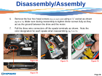
Disassembly/Assembly
8.
Lift the drive assembly partially off the motor and carefully pull each of the three wires
individually through the hole provided
(fig 73).
9.
Do not attempt to pull all three wires through the hole as you may cause damage.
Note the
hole size
(fig 74).
The bottom of the drive is called the heatsink
(fig 73 & 74).
During reassembly
make sure all three wires are pulled completely through the hole provided to prevent
pinching between the motor and the drive.
10.
The drive assembly is one sealed unit and cannot be disassembled.
It is replaced as an
assembly.
Make sure any debris is removed before reassembly.
Figure 73
Figure 74
Page 37
Heatsink