HP ENVY Rove 20-k014us HP ENVY Rove 20 Mobile All-in-One PC - Maintenance and - Page 31
Bottom cover
 |
View all HP ENVY Rove 20-k014us manuals
Add to My Manuals
Save this manual to your list of manuals |
Page 31 highlights
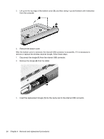
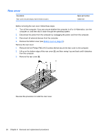
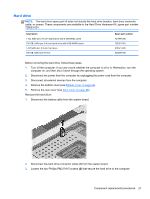
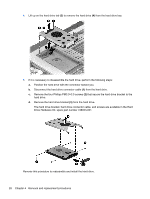
Bottom cover Description Bottom cover (includes 2 captive screws, secured by C-clips) Spare part number 728046-001 Before disassembling the computer, follow these steps: 1. Turn off the computer. If you are unsure whether the computer is off or in Hibernation, turn the computer on, and then shut it down through the operating system. 2. Disconnect the power from the computer by unplugging the power cord from the computer. 3. Disconnect all external devices from the computer. Remove the bottom cover: CAUTION: Before positioning the computer with the display screen facing down, make sure the work surface is clear of tools, screws, and any other foreign objects. Failure to follow this caution can result in damage to the display screen. 1. Position the computer with the display screen facing down and the bottom edge toward you. 2. Press in on the media card reader slot bezel (1) to release the bezel from the slot, and then press in on the bezel (2) a second time to remove the bezel from the slot. The media card reader slot bezel is included in the Rubber Kit, spare part number 728073-001. 3. Remove the two rubber screw covers (1). The rubber screw covers are included in the Rubber Kit, spare part number 728073-001. 4. Loosen the two Phillips PM2.5×5.0 captive screws (2) that secure the bottom cover to the computer. Component replacement procedures 23
-
 1
1 -
2
-
3
-
4
-
5
-
6
-
7
-
8
-
9
-
10
-
11
-
12
-
13
-
14
-
15
-
16
-
17
-
18
-
19
-
20
-
21
-
22
-
23
-
24
-
25
-
 26
26 -
 27
27 -
 28
28 -
 29
29 -
 30
30 -
 31
31 -
 32
32 -
 33
33 -
 34
34 -
 35
35 -
 36
36 -
37
-
38
-
39
-
40
-
41
-
42
-
43
-
44
-
45
-
46
-
47
-
48
-
49
-
50
-
51
-
52
-
53
-
54
-
55
-
56
-
57
-
58
-
59
-
60
-
61
-
62
-
63
-
64
-
65
-
66
-
67
-
68
-
69
-
70
-
71
-
72
-
73
-
74
-
75
-
76
-
77
-
78
-
79
-
80
-
81
-
82
-
83
-
84
-
85
-
86
-
87
-
88
-
89
 |
 |
