HP ENVY Rove 20-k014us HP ENVY Rove 20 Mobile All-in-One PC - Maintenance and - Page 43
Converter board, Disconnect the converter board ribbon cable
 |
View all HP ENVY Rove 20-k014us manuals
Add to My Manuals
Save this manual to your list of manuals |
Page 43 highlights
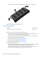
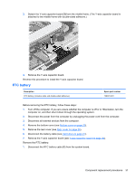
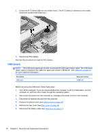
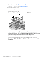
8. Remove the X-axis capacitor board (6) and cable. Reverse this procedure to install the X-axis capacitor board. Converter board NOTE: The converter board spare part kit does not include the converter board cable or converter board ribbon cable. The converter board cable and converter board ribbon cable are included in the Cable Kit, spare part number 728048-001. See Cable Kit on page 12 for more Cable Kit information. Description Converter board Spare part number 728067-001 Before removing the converter board, follow these steps: 1. Turn off the computer. If you are unsure whether the computer is off or in Hibernation, turn the computer on, and then shut it down through the operating system. 2. Disconnect the power from the computer by unplugging the power cord from the computer. 3. Disconnect all external devices from the computer. 4. Remove the bottom cover (see Bottom cover on page 23). 5. Remove the rear cover (see Rear cover on page 26). 6. Disconnect the battery cable (see Hard drive on page 27). 7. Remove the cover bracket (see X-axis capacitor board on page 33). Remove the converter board: 1. Disconnect the converter board ribbon cable (1) from the low insertion force (LIF) connector on the display assembly. 2. Disconnect the converter board cable (2) from the system board. 3. Release the converter board cable from the clips (3) built into the middle frame. Component replacement procedures 35
-
 1
1 -
2
-
3
-
4
-
5
-
6
-
7
-
8
-
9
-
10
-
11
-
12
-
13
-
14
-
15
-
16
-
17
-
18
-
19
-
20
-
21
-
22
-
23
-
24
-
25
-
26
-
27
-
28
-
29
-
30
-
31
-
32
-
33
-
34
-
35
-
36
-
37
-
 38
38 -
 39
39 -
 40
40 -
 41
41 -
 42
42 -
 43
43 -
 44
44 -
 45
45 -
 46
46 -
 47
47 -
 48
48 -
49
-
50
-
51
-
52
-
53
-
54
-
55
-
56
-
57
-
58
-
59
-
60
-
61
-
62
-
63
-
64
-
65
-
66
-
67
-
68
-
69
-
70
-
71
-
72
-
73
-
74
-
75
-
76
-
77
-
78
-
79
-
80
-
81
-
82
-
83
-
84
-
85
-
86
-
87
-
88
-
89
 |
 |
