HP ENVY Rove 20-k014us HP ENVY Rove 20 Mobile All-in-One PC - Maintenance and - Page 57
WLAN module, Remove the Phillips PM2.0×3.5 screw
 |
View all HP ENVY Rove 20-k014us manuals
Add to My Manuals
Save this manual to your list of manuals |
Page 57 highlights
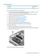
WLAN module Description Broadcom BCM4352 802.11ac 2×2 Wi-Fi + BT 4.0 Combo Adapter Spare part number 724935-005 CAUTION: To prevent an unresponsive system, replace the wireless module only with a wireless module authorized for use in the computer by the governmental agency that regulates wireless devices in your country or region. If you replace the module and then receive a warning message, remove the module to restore device functionality, and then contact technical support. Before removing the WLAN module, follow these steps: 1. Turn off the computer. If you are unsure whether the computer is off or in Hibernation, turn the computer on, and then shut it down through the operating system. 2. Disconnect the power from the computer by unplugging the power cord from the computer. 3. Disconnect all external devices from the computer. 4. Remove the bottom cover (see Bottom cover on page 23). 5. Remove the rear cover (see Rear cover on page 26). 6. Disconnect the battery cable (see Hard drive on page 27). 7. Remove the hard drive (see Hard drive on page 27). 8. Remove the cover bracket (see X-axis capacitor board on page 33). 9. Remove the display stand recess (see Display stand recess on page 41). Remove the WLAN module: 1. Disconnect the WLAN antenna cables (1) from the terminals on the WLAN module. NOTE: The #1/black WLAN antenna cable is connected to the WLAN module Main terminal. The #2/gray WLAN antenna cable is connected to the WLAN module Aux terminal. 2. Remove the Phillips PM2.0×3.5 screw (2) that secures the WLAN module to the system board. (The WLAN module tilts up.) Component replacement procedures 49
-
 1
1 -
2
-
3
-
4
-
5
-
6
-
7
-
8
-
9
-
10
-
11
-
12
-
13
-
14
-
15
-
16
-
17
-
18
-
19
-
20
-
21
-
22
-
23
-
24
-
25
-
26
-
27
-
28
-
29
-
30
-
31
-
32
-
33
-
34
-
35
-
36
-
37
-
38
-
39
-
40
-
41
-
42
-
43
-
44
-
45
-
46
-
47
-
48
-
49
-
50
-
51
-
 52
52 -
 53
53 -
 54
54 -
 55
55 -
 56
56 -
 57
57 -
 58
58 -
 59
59 -
 60
60 -
 61
61 -
 62
62 -
63
-
64
-
65
-
66
-
67
-
68
-
69
-
70
-
71
-
72
-
73
-
74
-
75
-
76
-
77
-
78
-
79
-
80
-
81
-
82
-
83
-
84
-
85
-
86
-
87
-
88
-
89
 |
 |
