HP ENVY Rove 20-k014us HP ENVY Rove 20 Mobile All-in-One PC - Maintenance and - Page 42
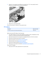
Remove the Phillips PM3.0×4.5 screw, from the system board.
 |
View all HP ENVY Rove 20-k014us manuals
Add to My Manuals
Save this manual to your list of manuals |
Page 42 highlights
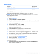
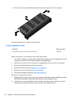
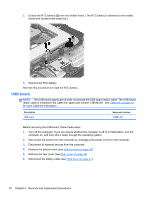
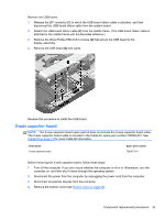
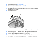
5. Remove the rear cover (see Rear cover on page 26). 6. Disconnect the battery cable (see Hard drive on page 27). Remove the X-axis capacitor board: 1. Remove the Phillips PM3.0×4.5 screw (1) and the two Phillips PM3.0×6.5 screws (2) that secure the cover bracket to the computer. 2. Remove the cover bracket (3). The cover bracket is available using spare part number 728054-001. 3. Release the two ZIF connectors (1) to which the two display panel ribbon cables are attached, and then disconnect the two display panel ribbon cables from the X-axis capacitor board. 4. Release the ZIF connector (2) to which the capacitor board ribbon cable is attached, and then disconnect the capacitor board ribbon cable from the X-axis capacitor board. 5. Disconnect the X-axis capacitor board cable (3) from the system board. 6. Release the X-axis capacitor board cable from the clips (4) built into the middle frame. 7. Remove the two Phillips PM2.5×3.0 screws (5) that secure the X-axis capacitor board to the middle frame. 34 Chapter 4 Removal and replacement procedures
-
 1
1 -
2
-
3
-
4
-
5
-
6
-
7
-
8
-
9
-
10
-
11
-
12
-
13
-
14
-
15
-
16
-
17
-
18
-
19
-
20
-
21
-
22
-
23
-
24
-
25
-
26
-
27
-
28
-
29
-
30
-
31
-
32
-
33
-
34
-
35
-
36
-
 37
37 -
 38
38 -
 39
39 -
 40
40 -
 41
41 -
 42
42 -
 43
43 -
 44
44 -
 45
45 -
 46
46 -
 47
47 -
48
-
49
-
50
-
51
-
52
-
53
-
54
-
55
-
56
-
57
-
58
-
59
-
60
-
61
-
62
-
63
-
64
-
65
-
66
-
67
-
68
-
69
-
70
-
71
-
72
-
73
-
74
-
75
-
76
-
77
-
78
-
79
-
80
-
81
-
82
-
83
-
84
-
85
-
86
-
87
-
88
-
89
 |
 |
