HP ENVY Rove 20-k014us HP ENVY Rove 20 Mobile All-in-One PC - Maintenance and - Page 68
Remove the fan see, Remove the system board see
 |
View all HP ENVY Rove 20-k014us manuals
Add to My Manuals
Save this manual to your list of manuals |
Page 68 highlights
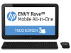
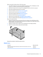
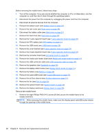
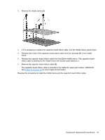
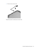
Before removing the middle frame, follow these steps: 1. Turn off the computer. If you are unsure whether the computer is off or in Hibernation, turn the computer on, and then shut it down through the operating system. 2. Disconnect the power from the computer by unplugging the power cord from the computer. 3. Disconnect all external devices from the computer. 4. Remove the bottom cover (see Bottom cover on page 23). 5. Remove the rear cover (see Rear cover on page 26). 6. Disconnect the battery cable (see Hard drive on page 27). 7. Remove the hard drive (see Hard drive on page 27). 8. Remove the Y-axis capacitor board (see Y-axis capacitor board on page 30). 9. Remove the RTC battery (see RTC battery on page 31). 10. Remove the USB board (see USB board on page 32). 11. Remove the cover bracket (see X-axis capacitor board on page 33). 12. Remove the X-axis capacitor board (see X-axis capacitor board on page 33). 13. Remove the converter board (see Converter board on page 35). 14. Remove the media card reader board (see Media card reader board on page 37). 15. Remove the USB connector cable (see USB connector cable on page 38). 16. Remove the speakers (see Speakers on page 39). 17. Remove the display stand recess (see Display stand recess on page 41). 18. Remove the battery (see Battery on page 44). 19. Remove the audio/USB board (see Audio/USB board on page 47). 20. Remove the air flow channel (see Air flow channel on page 51). 21. Remove the fan (see Fan on page 53). 22. Remove the system board (see System board on page 54). 23. Remove the display stand (see Display stand on page 58). Remove the middle frame: 1. Remove the eight Phillips PM3.0×6.5 screws (1) that secure the middle frame to the display assembly. NOTE: When removing the middle frame, make sure the display panel cable (2) routes cleanly through the opening in the middle frame. 60 Chapter 4 Removal and replacement procedures
-
 1
1 -
2
-
3
-
4
-
5
-
6
-
7
-
8
-
9
-
10
-
11
-
12
-
13
-
14
-
15
-
16
-
17
-
18
-
19
-
20
-
21
-
22
-
23
-
24
-
25
-
26
-
27
-
28
-
29
-
30
-
31
-
32
-
33
-
34
-
35
-
36
-
37
-
38
-
39
-
40
-
41
-
42
-
43
-
44
-
45
-
46
-
47
-
48
-
49
-
50
-
51
-
52
-
53
-
54
-
55
-
56
-
57
-
58
-
59
-
60
-
61
-
62
-
 63
63 -
 64
64 -
 65
65 -
 66
66 -
 67
67 -
 68
68 -
 69
69 -
 70
70 -
 71
71 -
 72
72 -
 73
73 -
74
-
75
-
76
-
77
-
78
-
79
-
80
-
81
-
82
-
83
-
84
-
85
-
86
-
87
-
88
-
89
 |
 |
