HP ENVY Rove 20-k014us HP ENVY Rove 20 Mobile All-in-One PC - Maintenance and - Page 38
Y-axis capacitor board, to which the capacitor board ribbon cable is attached, and then
 |
View all HP ENVY Rove 20-k014us manuals
Add to My Manuals
Save this manual to your list of manuals |
Page 38 highlights
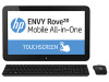
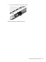
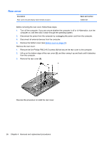
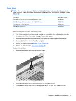
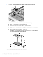
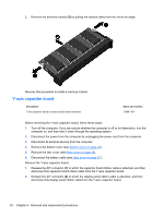
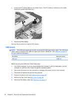
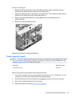
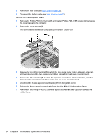
2. Remove the memory module (2) by pulling the module away from the slot at an angle. Reverse this procedure to install a memory module. Y-axis capacitor board Description Y-axis capacitor board (includes double-sided adhesive) Spare part number 728067-001 Before removing the Y-axis capacitor board, follow these steps: 1. Turn off the computer. If you are unsure whether the computer is off or in Hibernation, turn the computer on, and then shut it down through the operating system. 2. Disconnect the power from the computer by unplugging the power cord from the computer. 3. Disconnect all external devices from the computer. 4. Remove the bottom cover (see Bottom cover on page 23). 5. Remove the rear cover (see Rear cover on page 26). 6. Disconnect the battery cable (see Hard drive on page 27). Remove the Y-axis capacitor board: 1. Release the ZIF connector (1) to which the capacitor board ribbon cable is attached, and then disconnect the capacitor board ribbon cable from the Y-axis capacitor board. 2. Release the ZIF connector (2) to which the display panel ribbon cable is attached, and then disconnect the display panel ribbon cable from the Y-axis capacitor board. 30 Chapter 4 Removal and replacement procedures
-
 1
1 -
2
-
3
-
4
-
5
-
6
-
7
-
8
-
9
-
10
-
11
-
12
-
13
-
14
-
15
-
16
-
17
-
18
-
19
-
20
-
21
-
22
-
23
-
24
-
25
-
26
-
27
-
28
-
29
-
30
-
31
-
32
-
 33
33 -
 34
34 -
 35
35 -
 36
36 -
 37
37 -
 38
38 -
 39
39 -
 40
40 -
 41
41 -
 42
42 -
 43
43 -
44
-
45
-
46
-
47
-
48
-
49
-
50
-
51
-
52
-
53
-
54
-
55
-
56
-
57
-
58
-
59
-
60
-
61
-
62
-
63
-
64
-
65
-
66
-
67
-
68
-
69
-
70
-
71
-
72
-
73
-
74
-
75
-
76
-
77
-
78
-
79
-
80
-
81
-
82
-
83
-
84
-
85
-
86
-
87
-
88
-
89
 |
 |
