HP G32-200 Compaq Presario CQ32 Notebook PC and HP G32 Notebook PC - Maintenan - Page 79
Optical drive connector, Remove the Phillips PM2.0×3.0 screw
 |
View all HP G32-200 manuals
Add to My Manuals
Save this manual to your list of manuals |
Page 79 highlights
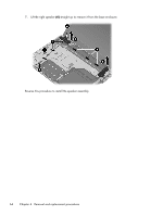
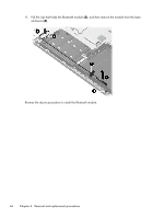
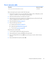
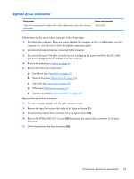
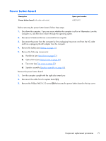
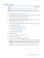
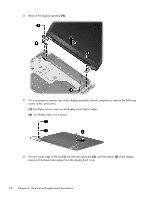
Optical drive connector Description Optical Drive Mounting Kit (includes SATA cable, cable bracket, optical drive bracket, and screws) Spare part number 608274-001 Before removing the optical drive connector, follow these steps: 1. Shut down the computer. If you are unsure whether the computer is off or in Hibernation, turn the computer on, and then shut it down through the operating system. 2. Disconnect all external devices connected to the computer. 3. Disconnect the power from the computer by first unplugging the power cord from the AC outlet and then unplugging the AC adapter from the computer. 4. Remove the battery (see Battery on page 41). 5. Remove the following components: a. Hard drive (see Hard drive on page 51) b. Optical drive (see Optical drive on page 54) c. Top cover (see Top cover on page 55) d. USB board (USB board on page 61). e. Speaker assembly(Speaker assembly on page 63). Remove the optical drive connector: 1. Turn the computer upright with the right side toward you. 2. Remove the tape that secures the cable to the base enclosure (1). 3. Disconnect the optical drive connector from the system board (2). 4. Remove the Phillips PM2.0×3.0 screw (3) that secures the optical drive connector to the base enclosure. 5. Lift the bracket from the base enclosure (4). Component replacement procedures 69
-
 1
1 -
2
-
3
-
4
-
5
-
6
-
7
-
8
-
9
-
10
-
11
-
12
-
13
-
14
-
15
-
16
-
17
-
18
-
19
-
20
-
21
-
22
-
23
-
24
-
25
-
26
-
27
-
28
-
29
-
30
-
31
-
32
-
33
-
34
-
35
-
36
-
37
-
38
-
39
-
40
-
41
-
42
-
43
-
44
-
45
-
46
-
47
-
48
-
49
-
50
-
51
-
52
-
53
-
54
-
55
-
56
-
57
-
58
-
59
-
60
-
61
-
62
-
63
-
64
-
65
-
66
-
67
-
68
-
69
-
70
-
71
-
72
-
73
-
 74
74 -
 75
75 -
 76
76 -
 77
77 -
 78
78 -
 79
79 -
 80
80 -
 81
81 -
 82
82 -
 83
83 -
 84
84 -
85
-
86
-
87
-
88
-
89
-
90
-
91
-
92
-
93
-
94
-
95
-
96
-
97
-
98
-
99
-
100
-
101
-
102
-
103
-
104
-
105
-
106
-
107
-
108
-
109
-
110
-
111
-
112
-
113
-
114
-
115
-
116
-
117
-
118
-
119
-
120
-
121
-
122
-
123
-
124
-
125
-
126
-
127
-
128
-
129
-
130
 |
 |