HP G32-200 Compaq Presario CQ32 Notebook PC and HP G32 Notebook PC - Maintenan - Page 90
Lift the right side of the system board, that secures the system board.
 |
View all HP G32-200 manuals
Add to My Manuals
Save this manual to your list of manuals |
Page 90 highlights
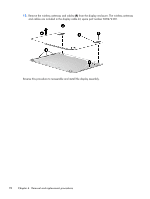
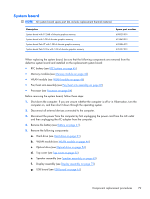
h. Power connector cable (see Power connector cable on page 67) i. Display (see Display assembly on page 73) 1. Turn the computer upright with the left side toward you. 2. Remove the two Phillips PM2.5×5.0 screws (1) that secure the system board to the computer. 3. Loosen the captive screw in the fan sink (2) that secures the system board. 4. Lift the right side of the system board (3). 5. Release the system board by sliding it to the right at an angle (4) until the connectors on the left side of the system board clear the base enclosure, and then remove the system board. Reverse the preceding procedure to install the system board. 80 Chapter 4 Removal and replacement procedures
-
 1
1 -
2
-
3
-
4
-
5
-
6
-
7
-
8
-
9
-
10
-
11
-
12
-
13
-
14
-
15
-
16
-
17
-
18
-
19
-
20
-
21
-
22
-
23
-
24
-
25
-
26
-
27
-
28
-
29
-
30
-
31
-
32
-
33
-
34
-
35
-
36
-
37
-
38
-
39
-
40
-
41
-
42
-
43
-
44
-
45
-
46
-
47
-
48
-
49
-
50
-
51
-
52
-
53
-
54
-
55
-
56
-
57
-
58
-
59
-
60
-
61
-
62
-
63
-
64
-
65
-
66
-
67
-
68
-
69
-
70
-
71
-
72
-
73
-
74
-
75
-
76
-
77
-
78
-
79
-
80
-
81
-
82
-
83
-
84
-
 85
85 -
 86
86 -
 87
87 -
 88
88 -
 89
89 -
 90
90 -
 91
91 -
 92
92 -
 93
93 -
 94
94 -
 95
95 -
96
-
97
-
98
-
99
-
100
-
101
-
102
-
103
-
104
-
105
-
106
-
107
-
108
-
109
-
110
-
111
-
112
-
113
-
114
-
115
-
116
-
117
-
118
-
119
-
120
-
121
-
122
-
123
-
124
-
125
-
126
-
127
-
128
-
129
-
130
 |
 |
h.
Power connector cable (see
Power connector cable
on page
67
)
i.
Display (see
Display assembly
on page
73
)
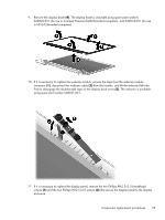
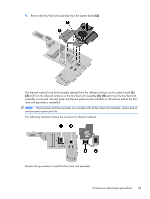
1.
Turn the computer upright with the left side toward you.
2.
Remove the two Phillips PM2.5×5.0 screws
(1)
that secure the system board to the computer.
3.
Loosen the captive screw in the fan sink
(2)
that secures the system board.
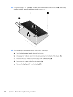
4.
Lift the right side of the system board
(3)
.
5.
Release the system board by sliding it to the right at an angle
(4)
until the connectors on the left
side of the system board clear the base enclosure, and then remove the system board.
Reverse the preceding procedure to install the system board.
80
Chapter 4
Removal and replacement procedures