HP G32-200 Compaq Presario CQ32 Notebook PC and HP G32 Notebook PC - Maintenan - Page 95
Turn the processor locking screw, one-half turn counterclockwise until you hear a click.
 |
View all HP G32-200 manuals
Add to My Manuals
Save this manual to your list of manuals |
Page 95 highlights
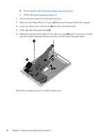
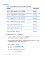
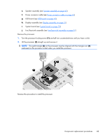
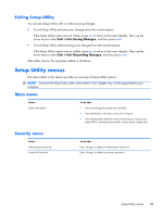
e. Speaker assembly (see Speaker assembly on page 63) f. Power connector cable (see Power connector cable on page 67) g. USB board (see USB board on page 61). h. Display assembly (see Display assembly on page 73) i. System board (see System board on page 79) j. Fan/heat sink assembly (see Fan/heat sink assembly on page 81) Remove the processor: 1. Turn the processor locking screw (1) one-half turn counterclockwise until you hear a click. 2. Lift the processor (2) straight up and remove it. NOTE: The gold triangle (3) on the processor must be aligned with the triangle icon (4) embossed on the processor socket when you install the processor. Reverse this procedure to install the processor. Component replacement procedures 85
-
 1
1 -
2
-
3
-
4
-
5
-
6
-
7
-
8
-
9
-
10
-
11
-
12
-
13
-
14
-
15
-
16
-
17
-
18
-
19
-
20
-
21
-
22
-
23
-
24
-
25
-
26
-
27
-
28
-
29
-
30
-
31
-
32
-
33
-
34
-
35
-
36
-
37
-
38
-
39
-
40
-
41
-
42
-
43
-
44
-
45
-
46
-
47
-
48
-
49
-
50
-
51
-
52
-
53
-
54
-
55
-
56
-
57
-
58
-
59
-
60
-
61
-
62
-
63
-
64
-
65
-
66
-
67
-
68
-
69
-
70
-
71
-
72
-
73
-
74
-
75
-
76
-
77
-
78
-
79
-
80
-
81
-
82
-
83
-
84
-
85
-
86
-
87
-
88
-
89
-
 90
90 -
 91
91 -
 92
92 -
 93
93 -
 94
94 -
 95
95 -
 96
96 -
 97
97 -
 98
98 -
 99
99 -
 100
100 -
101
-
102
-
103
-
104
-
105
-
106
-
107
-
108
-
109
-
110
-
111
-
112
-
113
-
114
-
115
-
116
-
117
-
118
-
119
-
120
-
121
-
122
-
123
-
124
-
125
-
126
-
127
-
128
-
129
-
130
 |
 |
e.
Speaker assembly (see
Speaker assembly
on page
63
)
f.
Power connector cable (see
Power connector cable
on page
67
)
g.
USB board (see
USB board
on page
61
).
h.
Display assembly (see
Display assembly
on page
73
)
i.
System board (see
System board
on page
79
)
j.
Fan/heat sink assembly (see
Fan/heat sink assembly
on page
81
)
Remove the processor:
1.
Turn the processor locking screw
(1)
one-half turn counterclockwise until you hear a click.
2.
Lift the processor
(2)
straight up and remove it.
NOTE:
The gold triangle
(3)
on the processor must be aligned with the triangle icon
(4)
embossed on the processor socket when you install the processor.
Reverse this procedure to install the processor.
Component replacement procedures
85