HP G32-200 Compaq Presario CQ32 Notebook PC and HP G32 Notebook PC - Maintenan - Page 91
Fan/heat sink assembly
 |
View all HP G32-200 manuals
Add to My Manuals
Save this manual to your list of manuals |
Page 91 highlights
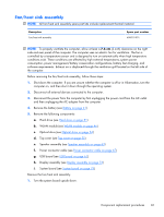
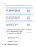
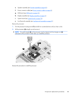
Fan/heat sink assembly NOTE: All fan/heat sink assembly spare part kits include replacement thermal material. Description Fan/heat sink assembly Spare part number 608010-001 NOTE: To properly ventilate the computer, allow at least a 7.6-cm (3-inch) clearance on the right side and rear panel of the computer. The computer uses an electric fan for ventilation. The fan is controlled by a temperature sensor and is designed to turn on automatically when high temperature conditions exist. These conditions are affected by high external temperatures, system power consumption, power management/battery conservation configurations, battery fast charging, and software requirements. Exhaust air is displaced through the ventilation grill located on the left side of the computer. Before removing the fan/heat sink assembly, follow these steps: 1. Shut down the computer. If you are unsure whether the computer is off or in Hibernation, turn the computer on, and then shut it down through the operating system. 2. Disconnect all external devices connected to the computer. 3. Disconnect the power from the computer by first unplugging the power cord from the AC outlet and then unplugging the AC adapter from the computer. 4. Remove the battery (see Battery on page 41). 5. Remove the following components: a. Hard drive (see Hard drive on page 51) b. WLAN module (see WLAN module on page 46) c. Optical drive (see Optical drive on page 54) d. Top cover (see Top cover on page 55) e. Speaker assembly (see Speaker assembly on page 63) f. Power connector cable (see Power connector cable on page 67) g. USB board (see USB board on page 61) h. Display assembly (see Display assembly on page 73) i. System board (see System board on page 79) Remove the fan/heat sink assembly: 1. Turn the system board upside down. Component replacement procedures 81
-
 1
1 -
2
-
3
-
4
-
5
-
6
-
7
-
8
-
9
-
10
-
11
-
12
-
13
-
14
-
15
-
16
-
17
-
18
-
19
-
20
-
21
-
22
-
23
-
24
-
25
-
26
-
27
-
28
-
29
-
30
-
31
-
32
-
33
-
34
-
35
-
36
-
37
-
38
-
39
-
40
-
41
-
42
-
43
-
44
-
45
-
46
-
47
-
48
-
49
-
50
-
51
-
52
-
53
-
54
-
55
-
56
-
57
-
58
-
59
-
60
-
61
-
62
-
63
-
64
-
65
-
66
-
67
-
68
-
69
-
70
-
71
-
72
-
73
-
74
-
75
-
76
-
77
-
78
-
79
-
80
-
81
-
82
-
83
-
84
-
85
-
 86
86 -
 87
87 -
 88
88 -
 89
89 -
 90
90 -
 91
91 -
 92
92 -
 93
93 -
 94
94 -
 95
95 -
 96
96 -
97
-
98
-
99
-
100
-
101
-
102
-
103
-
104
-
105
-
106
-
107
-
108
-
109
-
110
-
111
-
112
-
113
-
114
-
115
-
116
-
117
-
118
-
119
-
120
-
121
-
122
-
123
-
124
-
125
-
126
-
127
-
128
-
129
-
130
 |
 |