HP G32-200 Compaq Presario CQ32 Notebook PC and HP G32 Notebook PC - Maintenan - Page 89
System board, Remove the battery see
 |
View all HP G32-200 manuals
Add to My Manuals
Save this manual to your list of manuals |
Page 89 highlights
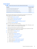
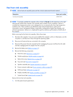
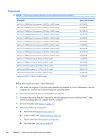
System board NOTE: All system board spare part kits include replacement thermal material. Description System board with 512-MB of discrete graphics memory System board with 1-GB of discrete graphics memory System board Park XT with 1-GB of discrete graphics memory System board Park S3 Pro with 1-GB of discrete graphics memory Spare part number 608029-001 615842-001 635226-001 635227-001 When replacing the system board, be sure that the following components are removed from the defective system board and installed on the replacement system board: ● RTC battery (see RTC battery on page 45) ● Memory modules (see Memory module on page 42) ● WLAN module (see WLAN module on page 46) ● Fan/heat sink assembly (see Fan/heat sink assembly on page 81) ● Processor (see Processor on page 84) Before removing the system board, follow these steps: 1. Shut down the computer. If you are unsure whether the computer is off or in Hibernation, turn the computer on, and then shut it down through the operating system. 2. Disconnect all external devices connected to the computer. 3. Disconnect the power from the computer by first unplugging the power cord from the AC outlet and then unplugging the AC adapter from the computer. 4. Remove the battery (see Battery on page 41). 5. Remove the following components: a. Hard drive (see Hard drive on page 51) b. WLAN module (see WLAN module on page 46) c. Optical drive (see Optical drive on page 54) d. Top cover (see Top cover on page 55) e. Speaker assembly (see Speaker assembly on page 63) f. Display assembly (see Display assembly on page 73) g. USB board (see USB board on page 61) Component replacement procedures 79
-
 1
1 -
2
-
3
-
4
-
5
-
6
-
7
-
8
-
9
-
10
-
11
-
12
-
13
-
14
-
15
-
16
-
17
-
18
-
19
-
20
-
21
-
22
-
23
-
24
-
25
-
26
-
27
-
28
-
29
-
30
-
31
-
32
-
33
-
34
-
35
-
36
-
37
-
38
-
39
-
40
-
41
-
42
-
43
-
44
-
45
-
46
-
47
-
48
-
49
-
50
-
51
-
52
-
53
-
54
-
55
-
56
-
57
-
58
-
59
-
60
-
61
-
62
-
63
-
64
-
65
-
66
-
67
-
68
-
69
-
70
-
71
-
72
-
73
-
74
-
75
-
76
-
77
-
78
-
79
-
80
-
81
-
82
-
83
-
 84
84 -
 85
85 -
 86
86 -
 87
87 -
 88
88 -
 89
89 -
 90
90 -
 91
91 -
 92
92 -
 93
93 -
 94
94 -
95
-
96
-
97
-
98
-
99
-
100
-
101
-
102
-
103
-
104
-
105
-
106
-
107
-
108
-
109
-
110
-
111
-
112
-
113
-
114
-
115
-
116
-
117
-
118
-
119
-
120
-
121
-
122
-
123
-
124
-
125
-
126
-
127
-
128
-
129
-
130
 |
 |
